
Abstract
In order to reduce the influence of noise on the stability of cyclic signal transmission and improve the effect of signal control, a method to control the stability of cyclic signal transmission of high-power driving circuit is proposed. The main components of the driving circuit and the characteristics of its cyclic signal are analyzed. According to the analysis results, a cyclic signal transmission interference detection module is designed, and the source interference detection is realized by using this module; Considering the electromagnetic influence of the circulating signal and the power part, the optocoupler isolation method is used to isolate the circulating signal; On the basis of detecting and isolating the transmission interference of circulating signal, the primary pulse width modulation signal and the secondary fault feedback signal are modulated by a single pulse transformer to realize the bidirectional transmission design of circulating signal; The internal optimization design of the high-power drive circuit is carried out, the error correction of the signal transmission stability control is carried out by using the linearized small interference error compensation method, and the empirical mode decomposition method is applied to the cyclic signal analysis of the high-power drive circuit to solve the cross term interference problem in the cyclic signal analysis. Finally, the stability control of cyclic signal transmission is realized by using double quasi PR controller. The experimental results show that the signal transmission time of this method is short, the minimum value is less than 0.5 s, the signal transmission deviation is only 0.22, the transmission rate is high, the signal transmission deviation is small, and the signal waveform is stable, which fully shows that its control effect is good.
Keywords
Introduction
In recent years, high-power driving circuits have developed rapidly. Therefore, it is of great practical significance to do a good job in signal transmission noise control [1]. Traditional methods usually take the advantages of high-power driving circuit as the starting point, analyze the main causes of cyclic signal noise of high-power driving circuit, and give the method of controlling signal transmission stability in combination with the actual situation, so as to ensure the normal operation of high-power driving circuit, provide reference for similar research and promote the further development of high-power driving circuit [2]. However, due to the continuous development of high-power driving circuit, the transmission speed of its cyclic signal is faster and faster. Among them, the signal quality and integrity have gradually become the focus of attention [3]. For high-power driving circuits, the existence of noise affects the signal transmission quality to a great extent. Therefore, technical improvement and structural optimization have become urgent problems to be solved [4].
Zhang and Wang [5] proposed the deviation control method of signal transmission under narrowband impedance matching based on decision feedback. Through the narrowband signal sampling theorem, the signal acquisition under narrowband impedance matching is realized by reducing the sampling frequency. According to the collected signal and considering that the deviation usually occurs under various interferences, the adaptive filter under double loop decision feedback is designed and constructed. In the deviation control, it is set that the system contains direct spread spectrum part to suppress the interference in signal transmission, and the decision feedback circuit is introduced to reduce signal distortion. The decision feedback system obtains the estimated value of the interference signal according to the transmission signal chip, and inputs the estimated value into the adaptive filter as a reference. By reducing the correlation between the reference signal and the direct spread part of the original signal, the decision feedback can better suppress the signal transmission interference under the narrowband impedance matching and reduce the signal distortion, so as to realize signal transmission deviation control. The experimental results show that this method can suppress all kinds of interference and realize the efficient control of signal transmission, but this method has the problem of low signal transmission rate. Yu et al. [6] aim at the complex problem of parameter matching of ship DC (Direct current) integrated power system, by establishing the system mathematical model, proposed the method of applying the small signal stability analysis based on state space equation to the design of control parameters in ship DC system. The stability of the system is analyzed when the control parameters change, and the stable region of the corresponding parameters is obtained, and a simulation model is built in the Digsilent/Power Factory environment to verify the validity of the conclusion, which provides support for the design of the control parameters of the system, but there are signals in this method, the problem of large transmission deviation. Li et al. [7] analyzed and compared the existing impedance analysis methods, compared the impedance ratio criteria used by different analysis methods, and selected the less conservative MPC (Modal Phase Collinearity) criterion as the small signal model of the micro gas turbine power generation system studied. The criterion of stable transmission control, and the shortcomings of the MPC criterion have been improved. The small signal models of two shaft gas turbine, generator rectifier and motor inverter in hybrid power system are established, and the small signal stability of hybrid power system is analyzed by impedance analysis method. Finally, a feedforward compensation method is proposed to improve the small signal stability of the system and solve the problem of small signal instability when the gas turbine is loaded with generator rectifier. However, this method is easily affected by interference factors and has the problem of poor control effect of signal transmission stability.
In order to solve the problems of low signal transmission rate, large signal transmission deviation and poor stability control effect, a new cyclic signal transmission stability control method of high-power driving circuit is proposed.
High power drive circuit
High-power drive circuit components
In the application of high-power equipment, it is particularly important to design a stable and reliable driving circuit. In this paper, 1200 V/200 A high power drive circuit is taken as an example for discussion. Figure 1 shows the main components of the drive circuit, including isolated input, preamplifier, power amplifier, protection circuit and grid resistance.
High-power drive circuit.
According to Fig. 1, when the drive module protection circuit is working, pin 5 outputs a low level to place the C-E terminals of the power drive circuit in a negative bias, and the power drive circuit is reliably turned off. At the same time, the 8-pin FAULT signal FO jumps from high level to low level. Among them, after the desaturation trigger level has passed the reset time of 1.25 ms, when the input control level is low, the protection circuit is reset, and FO jumps to a high level.
The statistical characteristics (such as correlation function, power spectrum, etc.) of the cyclic signal
In the formula,
Since the autocorrelation function
In the formula,
It can be seen from Eq. (2) that the cyclic autocorrelation function
The Fourier transform of the cyclic autocorrelation function
In the formula,
According to the analysis results of the high-power drive circuit, the characteristics of the cyclic signal are obtained. Based on this, the signal transmission stability control is studied from the perspective of anti-interference.
Circular signal transmission interference detection
Under the normal working state of high-power driving circuit, if the power supply system is constantly disturbed, the working state of internal digital logic (high working frequency) is bound to be affected, and even lead to functional disorder. By detecting the fluctuation of the power supply system, the working state of the high-power driving circuit is determined to avoid working under the continuous interference state. The system power supply shall be selected for the interference detection signal. During the design, it shall be noted that the detection mechanism shall be placed close to the power supply to ensure that the interference can be detected at the source. The design of interference detection module is required to respond to the changes of high-power driving circuit, and constantly refresh the current results to prepare for the next detection. Combined with the above characteristics, the design of this module is shown in Fig. 2.
Logic diagram of cyclic signal transmission interference detection module.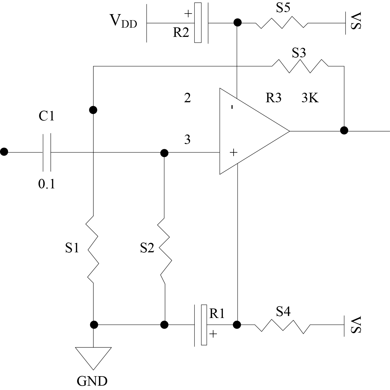
When the refresh signal is invalid (set low), when there is spike interference on the power supply (design index: positive spike interference
The interference detection module can continuously refresh the signal output by the interference detection module in the normal state and make corresponding judgment, so that the high-power driving circuit can stop working in the case of interference and resume normal operation after the interference is removed.
In the practical application of high-power driving circuit, due to the great potential difference between the circulating circuit and the main circuit, the electromagnetic influence of the circulating signal and the power part must be considered. Therefore, the circulating signal needs to be isolated and transmitted. At present, there are four isolation modes of high-power driving circuit: level shift, optocoupler isolation, optical fiber isolation and pulse transformer isolation. Among them, optocoupler isolation is the most widely used and technologically mature isolation mode at present. Considering that high-power driving circuits are often used in high-frequency conditions, and the transmission delay is high in high-frequency conditions, a new optocoupler isolation method is adopted in this paper [11].
Figure 3 shows the four-pin optocoupler lead diagram commonly used in optocoupler isolation.
Common four-pin optocoupler lead diagram for optocoupler isolation.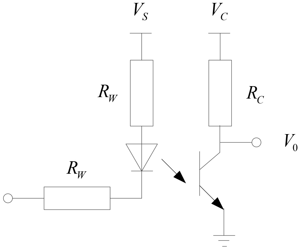
In Fig. 3, the potential difference between the circulating signal and
Equivalent circuit diagram.
The output voltage
In the formula,
Based on the interference detection and isolation of cyclic signal transmission, the bidirectional transmission of cyclic signal is designed. In the high-power driving circuit, the primary signal is isolated through the transformer after modulation, and demodulated as the driving signal of the gate pole in the secondary. When the secondary detects a fault, the driving circuit stops working. If the fault signal is transmitted to the primary, another magnetically isolated feedback circuit needs to be designed. Therefore, this paper proposes a bi-directional transmission of primary pulse width modulation (PMW) signal and secondary fault feedback signal through a single pulse transformer, which can reduce the wiring area of printed circuit board of driving circuit and the energy loss in the process of signal transmission, and strengthen the anti-interference ability of high-power driving circuit. The reliability of the magnetic isolation driving circuit is verified by high-power driving experiments. Some key functions of the driving circuit can realize integrated circuit and reduce the volume.
On the basis of synchronous pulse group modulation and demodulation, the fault signal feedback function is added to the whole circuit. The driving signal and fault signal can share the same magnetic isolation circuit. The bidirectional transmission block diagram of cyclic signal is shown in Fig. 5.
Block diagram of bidirectional transmission of cyclic signal.
It can be seen from Fig. 5 that the PMW signal is modulated into a synchronous pulse group by a digital circuit, and after being isolated by a pulse transformer, it is demodulated in the secondary as the driving signal of the high-power driving circuit. When the secondary detects a driving fault, it will stop outputting the driving signal. At the same time, the fault signal is transmitted to the primary through the pulse transformer. After the primary detects the fault signal, it is fed back to the input terminal and the PMW signal is blocked.
Internal optimization design
Because the noise has a great impact on the cyclic signal transmission of high-power driving circuit, it will not only reduce the transmission rate, but also affect the quality of the signal. Therefore, in the design of high-power driving circuit, it is necessary to adjust the internal components of different systems according to the actual transmission requirements, so as to ensure the rationality of the internal structure. The volume of the circuit has a direct impact on the function of the whole circuit. Therefore, the noise treatment needs to pay attention to the internal optimization design and configure the relationship between components and circuits, so as to improve the signal transmission quality. The following is the specific scheme of internal optimization design of high-power driving circuit:
When designing the inner board of circuit board, need to pay attention to the layout design of components, which should not only meet the needs of integration, but also effectively control the electromagnetic and other effects between components, so as to reasonably control the density of components, ensure that different components can be ventilated in time, ensure the quality of circular signal transmission, and prolong the service life of components; Pay attention to the optimization of circuit system, especially the improvement of heat dissipation, ensure the stability of power supply, and effectively avoid local overheating and high temperature and high voltage affecting the performance of components; In the process of internal optimization design, it is necessary to do a good job in the installation of wiring, reduce the electromagnetic coupling effect and reduce the public impedance as much as possible, so as to effectively avoid the occurrence of noise; Do a good job in grounding design to ensure the stability and safety of circuit structure.
On the basis of the analysis of the high-power drive circuit and the optimal design of the circuit, the improved design of the control method for the cyclic signal transmission stability of the high-power drive circuit is carried out. In order to improve the stability of the cyclic signal transmission of the high-power drive circuit, a stable control method of the cyclic signal transmission of the high-power drive circuit is proposed based on linearization small disturbance error compensation and PID self-tuning parameter adjustment [12, 13].
The error compensation method based on linearization small disturbance error is used to correct the error in the signal transmission stability control. The transfer function analysis method is usually used in the signal transmission control process [14]. Considering the existence of uncertain factors, the high-power drive circuit loop can be obtained. The transfer function of the signal is:
In the formula,
In the formula,
Solve the coefficients of the above formula separately, decompose the disturbance vector received by the circulating signal of the high-power drive circuit into a definite part and an uncertain part, and obtain the signal state feedback control model as follows:
In the formula,
The idea of tracking filtering is introduced for signal interference filtering, linearized small disturbance error compensation is performed, and a time-delay two-degree-of-freedom control active disturbance rejection tracker is constructed:
In the formula,
Suppose the input vector of the circulating signal of the high-power drive circuit is
In the formula,
Thus, under continuous disturbance, the linearized small disturbance error compensation control output is obtained:
In the formula,
The maximum sensitivity of cyclic signal tracking of high-power driving circuit is obtained by adjusting transmission attenuation
Furthermore, the empirical mode decomposition method is applied to the analysis of the cyclic signal of the high-power drive circuit to solve the problem of cross-term interference in the analysis of the cyclic signal [15].
In order to obtain the instantaneous parameters of signal
In the formula,
In the formula,
Equations (11) to (13) are the derivation process of cross-term interference suppression. Through the above steps, the steps of empirical mode decomposition are summarized as follows [16]:
(1) Use the cubic spline function to fit the maximum and minimum values of sequence
(2) Modulus decomposition, in this step, a decomposition condition
If
(3) After obtaining the first component, take the residual amount of
In order to realize residual discrimination, an intrinsic mode function is defined. The intrinsic mode function satisfies the boundary conditions of Hilbert transform. The defined conditions are: ⟀ In the sequence, the number of extreme points and zero-crossing points differ by at most 1; ⟁ At any point in the sequence, the mean value of the upper and lower envelopes formed by the maximum and minimum extreme points respectively is 0.
After the signal
In the formula,
In the formula,
Through the above analysis, it can be seen that the empirical mode decomposition process can decompose the fluctuations of different scales in the signal; According to the method of empirical mode decomposition, it can be understood that empirical mode decomposition is to extract the fast-varying fluctuation components of the signal from the slow-varying fluctuation components layer by layer.
Since the amplitude of the output impedance of the cyclic signal has a peak at a specific frequency, according to the impedance matching criterion, if the output impedance passes through the equivalent impedance of the circuit node, the transmission of the cyclic signal may be unstable. In order to reduce the potential crossover risk and improve the stability of cyclic signal transmission. This paper proposes a cyclic signal transmission stability control method based on a dual quasi-PR controller. The virtual harmonic impedance
The dual quasi-PR controller is composed of two quasi-PR controllers in series, and its transfer function
In the formula,
Analyze the resonance point frequency and its amplitude of the dual quasi-PR controller, and its expression is as follows:
The magnitude of
Through the above steps, it can be known that the maximum amplitude of the dual quasi-PR controller occurs at
To sum up, the control of the transmission stability of the cyclic signal is realized through the internal optimization design of the high-power circuit, the cyclic signal error compensation control and the cross-term interference suppression.
In order to verify the reliability of the stable control method of cyclic signal transmission in high-power drive circuit, saber simulation is carried out to verify the signal transmission. In the experiment, the narrowband impedance matching signal transmission deviation control method based on decision feedback and the small signal stability control method based on state space equation are compared with this method, and the experimental results verify the effectiveness of this method.
Experimental environment and parameter settings
The experiment was carried out under the hardware conditions of Intel Core-M480I5CPU@2.67 GHz, 8 GB memory, 64-bit operating system and Windows 10 system. The simulation experiments are built on the Saber platform to maximize the accuracy of the experimental results. Table 1 shows the set experimental parameters.
Experimental parameters
Experimental parameters
The experimental analysis was carried out under the above experimental environment and parameter settings.
(1) Signal transmission deviation
In order to verify the control effect of the cyclic signal transmission stability, the signal transmission deviation was used as the comparison index to compare the control effects of different methods. The results are shown in Fig. 6.
Comparison results of signal transmission deviation.
According to Fig. 6, as the number of experiments increases, the signal transmission deviation of different methods decreases. When the number of experiments is 3 times, the signal transmission deviation of the decision feedback method is 0.35 s, the signal transmission deviation of the state space equation method is 0.37 s, and the signal transmission deviation of the proposed method is only 0.24 s; when the number of experiments is 5 times, the signal transmission deviation of the decision feedback method is 0.33 s, the signal transmission deviation of the state space equation method is 0.33 s, and the signal transmission deviation of the proposed method is only 0.22 s. It can be seen that the signal transmission deviation of the proposed method is low, indicating that the proposed method has a better control effect on the cyclic signal transmission stability of the high-power drive circuit.
(2) Signal transmission rate
The control effect of different methods is further verified, and the signal transmission rate is used as the evaluation index, and the comparison results of the signal transmission rate of different methods are obtained as shown in Fig. 7.
Comparison results of signal transmission rates.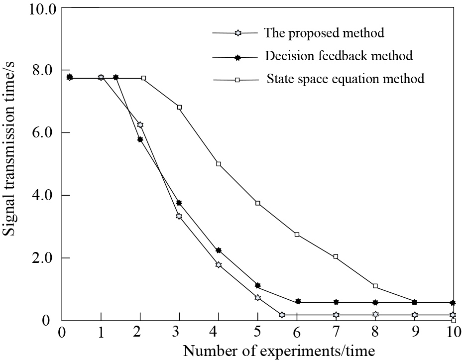
Signal change waveform.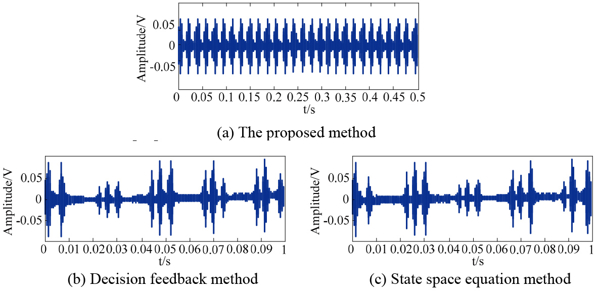
It can be seen from Fig. 7 that the signal transmission time is used as the evaluation index of the signal transmission rate, and the shorter the signal transmission time, the faster the signal transmission rate. According to the experimental results, at the beginning of the experiment, the signal transmission time of the three methods remained at a relatively stable level. With the deepening of the experiment, the signal transmission time of the three methods showed a trend of sharp decline. The signal transmission time of the method is shorter, and the lowest value is lower than 0.5 s. It can be seen that the signal transmission time of the proposed method is shorter, indicating that the signal transmission rate of the proposed method is higher.
(3) Signal stability analysis
The change waveform of the signal can best reflect the control effect of the cyclic signal transmission stability of the high-power drive circuit. Figure 8 is a waveform diagram of the signal stability control effect of different methods.
According to Fig. 8, it can be clearly seen by comparing (a), (b) and (c) in Fig. 8 that after the control of the proposed method, the circulating signal transmission waveform of the high-power driving circuit is dynamically stable, the fluctuation amplitude is regular, and the distorted current waveform is basically not. Therefore, the proposed method has good control effect. Under the control of decision feedback method and state space equation method, the circulating signal transmission waveform of high-power driving circuit fluctuates greatly, and there is the problem of signal instability.
In order to improve the signal transmission rate, reduce the signal transmission deviation, and improve the signal waveform stability as research purposes, a control method for the cyclic signal transmission stability of the high-power drive circuit is proposed. The main research contents of this method are summarized as follows:
Analyze the main components of the drive circuit and their cyclic signal characteristics, design a cyclic signal transmission interference detection module, use this module to realize signal interference detection, and reduce the influence of interference factors on the signal; The cyclic signal is isolated and transmitted by the optocoupler isolation method. On the basis of the interference detection and isolation of the cyclic signal transmission, the bidirectional transmission of the cyclic signal is designed; Through the internal optimization design of the high-power drive circuit and the correction of control errors, the problem of cross-term interference in the analysis of the cyclic signal is solved; The dual quasi-PR controller is used to realize the stability control of cyclic signal transmission; The experimental results show that the proposed method effectively solves the problems existing in the traditional method, the transmission rate is high, the signal transmission deviation is small, and the signal waveform is relatively stable, which verifies its reliability.
In order to further improve the robustness of the proposed method, the proposed algorithm is improved in the following research to improve the control accuracy of cyclic signal transmission stability of high-power drive circuit.