
Abstract
This paper presents a robust fuzzy control scheme for maximum power tracking of a photovoltaic (PV) pumping system dedicated to domestic use. This system is composed of a photovoltaic generator (PVG) supplying via a DC-DC boost converter, a DC motor coupled to a centrifugal pump. A knowledge dynamic model of the pumping system is firstly developed leading to a Takagi Sugeno (TS) representation by a simple convex polytopic transformation. This approach allows to reproduce the dynamic behavior of the system with accuracy over a wide operating range. Then, a robust T-S fuzzy MPPT controller is designed to track the reference speed and achieve an optimal operation of the photovoltaic pumping system. The proposed controller generates the optimal duty cycle to match the motor-pump impedance with the PV generator via a DC-DC converter, and thus, maximizes the quantity of water pumped daily. Finally, simulation results which take into account all changes in climatic conditions are presented for both transient and steady state operation.
Keywords
Introduction
Interest in the exploitation of solar energy has grown rapidly in recent decades due mainly to its direct availability with neither pollution nor noise,... In southern Tunisia, solar energy is abundant, an average insolation of 7 kWh/m2/day with more than 3200 hours of sunshine per year [15]; the surface water resources are limited, but the underground water resources are important. In addition, a large part of the population is scattered around a certain number of small villages has a limited access to the conventional forms of energy; their water needs are relatively low, and corresponding to a moderate consumption of water that satisfies some domestic use. All these factors encouraged the government to think about “Solar water”. In Tunisia, the main constraint hindering the use of photovoltaic pumping technology has rather been a financial problem. As a result, an economical program has been developed to exploit these natural resources using the photovoltaic generator as an electric power source for water pumping. Really, the majority of these programs get the needed investment from the technical cooperation projects, especially with Germany. For example, a micro solar plant for pumping and for the irrigation of a palm grove of 105 hectares was installed in the region of Kebili [14]. The project consists in installing 14 photovoltaic pumps financed by the German Agency for Cooperation (GIZ).
In the literature, several works have been proposed on the adequate choice of electrical drive system which can be used for photovoltaic pumping and which is best adapted to the Saharan regions [1–4, 17]. Based on a fuzzy logic control (FLC) scheme, a comparative study of the global efficiency of the PV water pumping systems using several types of motors is proposed in [10]. It has been shown that the permanent magnet synchronous motor (PMSM) is the appropriate electric moto-pump which gives the best global efficiency, and thus provides the largest quantities of water pumped daily. An optimal control strategy for operating the PV pumping system which is composed of an induction motor driving a centrifugal pump has been introduced in [2]. The proposed control scheme includes an LQR regulator, with an integral action performance allowing to improve the motor efficiency (minimum losses) and to maximize the pumped amount of water. In the same context, a comparative study of directly coupled photovoltaic pumping system and a constant voltage based-MPPT algorithms is presented in [12]. It has been noted that the use of a DC converter for tracking the maximum power point leads to a large transfer of available PV power especially at low temperatures.
Recently, a multi-model approach has been proposed to deal with the maximum power tracking problems in PV pumping systems by using TS models [5, 13]. It is based on the decomposition of the dynamic behavior of the system into several zones of operation, each characterized by a linear submodel of reduced complexity [8, 16]. Among the multiple interests of using this kinds of modeling are: first achieving a good compromise between accuracy and complexity of model, and second, reproducing the dynamic behavior of the system with accuracy over a wide operating range.
The major contribution of this work is the design of a robust MPPT fuzzy controller able to obligate the PV generator to operate very close to the maximum power trajectory. The proposed approach requires the use of a reference model speed which generates the optimal speed computed from the predetermined optimal power. This reference speed trajectory is employed in a feedback control loop that uses a fuzzy PI controller delivering the duty ratio used for the control of the boost converter. A conventional MPPT algorithm like P&O, Ind-Cond and a fuzzy logic controller are all used and compared with the given TS fuzzy approach under different climatic conditions.
Description and modeling of the system
The photovoltaic pumping system used in this work is consists of a PV generator, a DC-DC converter and a separately excited DC motor coupled to a centrifugal pump. The system is depicted in Fig. 1 and the mathematical models are developed in the following sections.

Fuzzy control diagram of the photovoltaic water pumping system.
Solar panels are made up of several solar cells arranged in series and/or in parallel to form a PV module able to generate the desired power. The combination of several photovoltaic modules electrically interconnected forms a continuous source known as a photovoltaic generator (PVG). The PVG used in this study is composed of 4 LC120P PV modules connected in series with 2 strings joined in parallel. The electrical characteristics of each PV module under standard conditions (i.e. T = 25°C, E = 1000 W/m2, AM = 1.5) are given in Table A1 Appendix A.
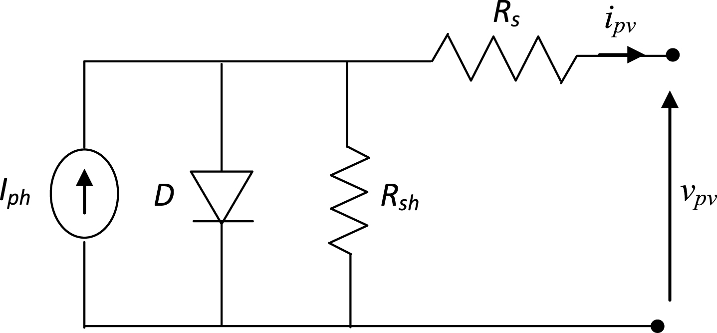
PV circuit model.
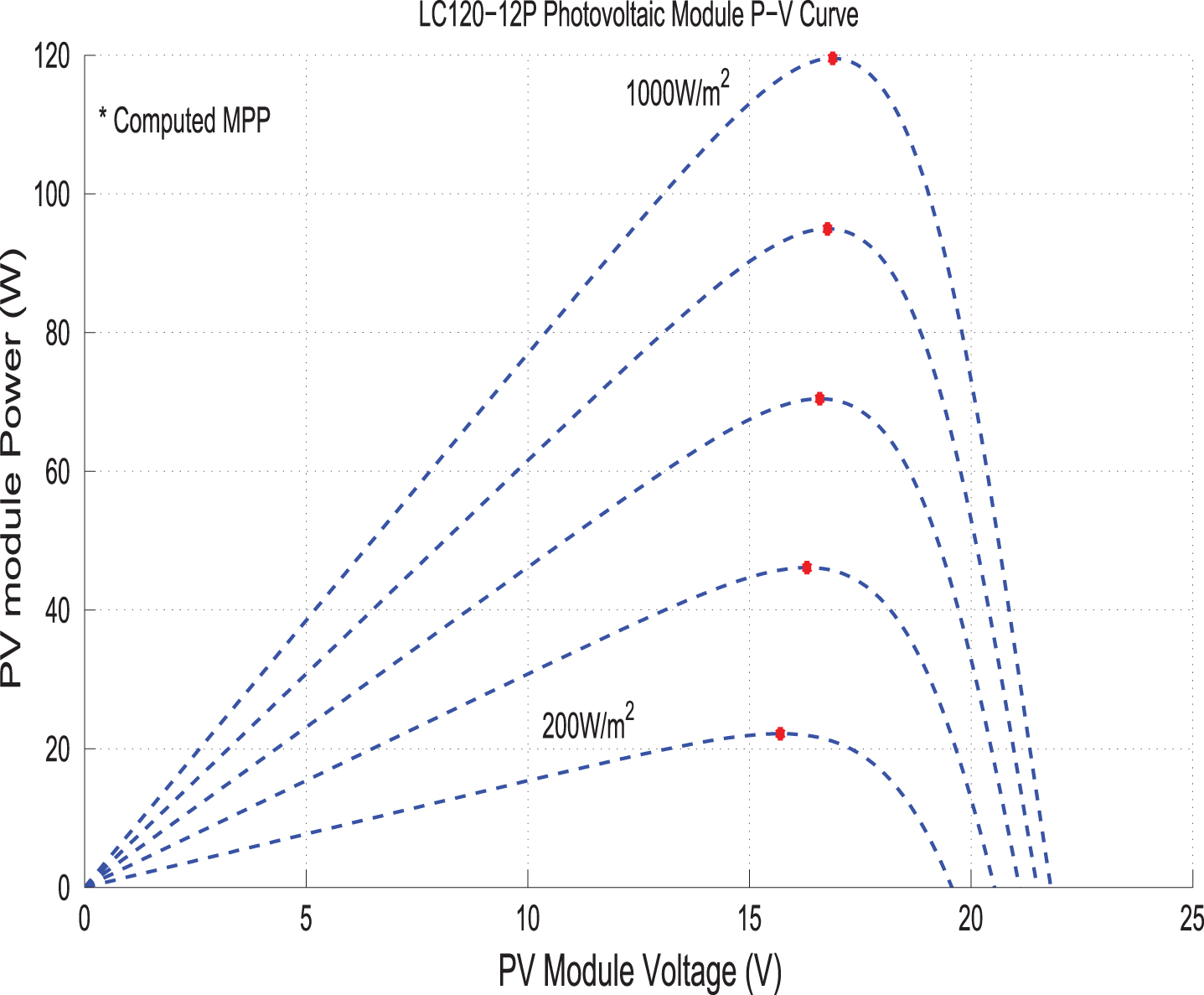
PV characteristics.

DC motor boost converter circuit.
According to Fig. 2, the current-voltage (I-V) characteristic of the PV cell is given as follows:
Figure 2 show the characteristics curve of the PV module power related to the PV voltage for different value of solar irradiation E (W/m2).
In the next section, we are going to view the dynamic model of the DC converter coupled to the DC motor-pump to infer the Takagi-Sugeno model that we would use in the controller design step.
In order to improve the global efficiency of the PV pumping system, a DC-DC converter is introduced between the PV generator and moto-pump. This boost converter known as a maximum power point tracker (MPPT) is used to match the impedance of the DC motor-pump to the PV generator. The global electrical circuit of the PV pumping system is shown in Fig. 2. The choice of DC motor drive in pumping system is related to its direct and easy coupling to the PV source. Additionally, the PV generator produces a continuous current, so using a DC motor would eliminate the need for a power inverter.
The motor voltage and torque equations under steady-state condition are:
The mechanical equation is:
The dynamic behavior of the overall boost converter circuit connected to the DC motor-pump is described by two linear differential equations depending of the switcher position. The first circuit topology is obtained when the switch position function is set to u = 1, and the second circuit topology is obtained when the switch position function is set to u = 0. Let’s consider the PV voltage v
pv
(t), the output voltage vc2 (t), the inductor current i
L
(t) and the rotor speed ω
m
(t) to be taken as state variables, the dynamic behavior during the ON period (u = 1) is given as follows:
And becomes during the OFF period (u = 0)
Consequently, the overall boost converter-DC motor dynamic is then reformulated in the following state spaces form:
If we introduce the duty ratio u(t) ∈ [0,1] during the two operational periods, the average dynamic model is given as follows:
Centrifugal pumps are widely used for photovoltaic pumping applications because they are designed for high flow-rates and low or medium depths (10 to 100 m). The flow-rate is proportional to the rotational motor speed while the manometric head is proportional to the square of the speed. The centrifugal pump is known by the head-flow rate H(Q) characteristic curve which depends on the motor speed value [2, 10]:
Besides, the total manometric head (H) of a centrifugal pump which designates the pressure difference in meters between the aspiration and discharge ports can also be calculated as follows:
Where
H
g
is the static head representing the difference between the free level of the water to pump and the highest point of the canalization. The second term
H
c
in (13) designates the head losses due to the friction of the water on the duct’s walls; it is proportional to the square of the flow-rate and is defined as follows [10]:
To search the optimum operating point corresponding to the maximum power delivery for different levels of insolation and temperature, an MPP searching bloc is added which leads to compute instantly the partial derivative of power with respect to PV cell current. Here, the insolation and the temperature are evaluated and then transferred to the MPP searching bloc which generates the reference maximum power P opt . The later is considered as an input control for the reference speed model which provides the desired speed ω m opt to be tracked.
First, Let us define the electrical power equation absorbed by the DC motor as follows:
The torque-speed characteristic C
p
of the centrifugal pump is assumed to be proportional to the square of the motor speed as follows:
Equation (18) leads to the armature motor current expression as follows:
Then, and by replacing Equations (19) in (16), the DC electrical power can be expressed only as a function of the motor speed in the following form:
Assuming that the DC converter is ideal, if the maximum power point of the PVG is reached, then the optimal motor speed can be obtained on-line via Equation (21), and this can be done by adopting P
a
= P
opt
:
To ensure that the PV system operates at maximum power point at different climatic conditions and thus a significant part of the available solar power is transfered to the motor-pump, it is essential to ensure that the following expression is verified
Let us note I
opt
as the optimal value current when the power of the PV generator reaches the maximum value. By replacing v
pv
and
By solving equation(24) under the Matlab environment, the optimal current can easily calculated on-line. By introducing the pre-calculated I
opt
in Equation (2), we get the optimal voltage as follows:
A simplified insolation model is proposed to estimate the solar irradiance for a standard climatic condition [2, 3]:
The sunrise time is chosen as: t sr = 6 h.00.
The daily pumped water quantity is defined as [2, 3]:
The Takagi-Sugeno models are considered as universal approximators which can perfectly describe the dynamic behaviour of the nonlinear system [8, 17]. They make it possible to represent the nonlinear dynamic system under a convex combination of linear subsystems which are considered as a local submodels. Each sub-model contributes to the overall fuzzy model through weighting functions. So, according to the dynamic model (Equation 11), the sector of nonlinearities of the terms z
k
(t) = x
k
(t) ∈ [zkmin, zkmax], k ={ 1, 2, 3 } associated to the matrix B(x(t)) are:
The weighting functions of the proposed TS fuzzy model are:
The global fuzzy model is inferred as follows:
The TS fuzzy model structure (30) in which the parametric uncertainties are considered will be rectified as follows:
ΔA2 and ΔB
i
designate the parametric uncertainties that verify the norm-bounded condition:
The following section is reserved for the synthesis of a robust fuzzy controller that delivers the optimal duty cycle considered here as a control input for the power switcher.
To operate at the maximum power point, we have to impose the tracking error e (t) = (ω
mopt
(t) - ω
m
(t)) to converge to zero for all varying insolation and temperature levels. If this condition is achieved, the system reaches the maximum power operational point, which satisfies (dP
pv
/i
pv
) = (dP
pv
/v
pv
) = 0. In order to improve the fuzzy controller’s performance, an integral action is applied to the speed tracking error via the following equation:
So, we define the new fuzzy augmented representation as follows:
In this study, the main idea is to design a robust MPPT fuzzy controller able to obligate the PV generator to operate very close to the maximum power trajectory regardless of parameter variations and climatic change conditions. Hence, the trajectory tracking problem is converted to a fuzzy state feedback control, for which the proposed control law is given by:
Substituting the control law (35) in the fuzzy model (34), the closed loop system is given by:
Hence, the purpose of this study is to determine a TS fuzzy controller (35) with the H∞ performance (37) able to force the PV pumping system to operate very close to its maximum power trajectory for all parameter uncertainties and solar insolation change. The main result is stated in the following theorem.
Then, the H∞ performance is guaranteed for all disturbed solar insolations and the controller gains are obtained by
To evaluate the effectiveness of the designed MPPT fuzzy controller, simulation results of the closed loop system are performed with the PV pumping system. A comparative study has been made between the proposed TS fuzzy controller, the fuzzy logic controller, the Incremental and conductance (Inc-Cond) algorithm and the conventional perturb and observe (P&O) algorithm under variable solar insolation levels. Here, we use a Lorentz solar PV module LC120-12P, whose specifications are listed in Table 2. The boost converter parameters are chosen as L = 10 mH, R
L
= 0.01 Ω, C1 = 500 μF and C2 = 100 μF, where all the PV pumping system parameters are assumed with a 5% deviation. The controller gains are obtained by solving the LMI (38) and (39) as follows:
A fuzzy logic algorithm based on linguistic rules describing the operator’s control strategy is used to control the boost converter for the MPPT object. A typical fuzzy logic based MPPT controller is composed of three components: fuzzification, module interface and defuzzification. The proposed system is consist of two inputs: a variables error (E) and a change of error (CE), and one output, a variable duty cycle (u). The variable (E) and the (CE) are expressed as follows:
The space of (E) and (CE) is partitioned with fuzzy subset functions named NB (negative big), NS (negative small), ZE (zero), PS (positive small), and PB (positive big). The fuzzy controller membership for both inputs and output variables are triangle-shaped functions. Table 1 shows the rule table for the fuzzy logic controller design. Figure 5 shows the influence of the insolation variation on the PV generation power by using the proposed TS fuzzy controller, FL controller, Ind-cond algorithm and P&O algorithm.
Definition of happiness [12]

PV power generator and PV power generator zoomed.
The same figure includes the reference PV power value for comparison. It is shown that the proposed controller presents a smoother response, a suitable dynamic and a less steady state error. P&O algorithm leads to a larger oscillation especially when the insolation level increases and their is a non exact MPP tracking trajectory. Likewise, the Inc Cond method is affected by the same factors as the P&O method involving a compromise between steady-state oscillations and tracking speed to achieve a maximum power point.
Figure 6 shows the motor power for the same insolation profile. Alls proposed techniques exhibit an acceptable dynamic response, but the TS fuzzy one provides more power to the DC motor and this becomes visible especially when the insolation level increases to 1000 W/m2, which leads to maximizing the global efficiency of the PV puming system.
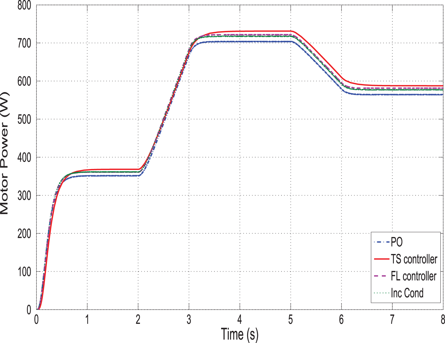
Motor power curve.
Figure 7 illustrates the duty cycle curve tuned by the fuzzy controller and calculated for different values of solar radiation levels. As it can be seen that the DC/DC duty cycle changes automatically with the insolation levels variation, this ensures an optimum matching of the load to the PV generator and consequently the operation of the PV system close to the MPP trajectory. The other MPPT techniques present a low tracking error especially at the 500 W/m2 insolation levels.

Duty cycle curve.
Figure 8 presents the reference motor speed obtained after solving Equation (21), which ensures a maximum power operation of the PVG for different insolation levels. It may be noted that the motor speed follows accurately the reference signal, which allows to operating in the required maximum power trajectory, mainly at the nominal value of insolation, in which the rotor speed reaches the value of 184.6 rd/s at 1000 W/m2. This can induce a significant amount of the total daily water pumped by the PV system. Figure 9 show the pump’s flow-rate obtained by equalizing Equations (12) and (13). Using the proposed TS fuzzy controller, the moto-pump starts to discharge water at the instant 0.28 (s). As a result, the water pumping cannot overcome the static head Hg = 7.4 m until a threshold insolation level of 295.6 W/m2 is achieved and it can pump the water only when a specific speed value is reached (122.6 rd/s). In this case, the electric power transferred to the moto-pump corresponding to this threshold is 290 W, about 30% of the rated PVG power.
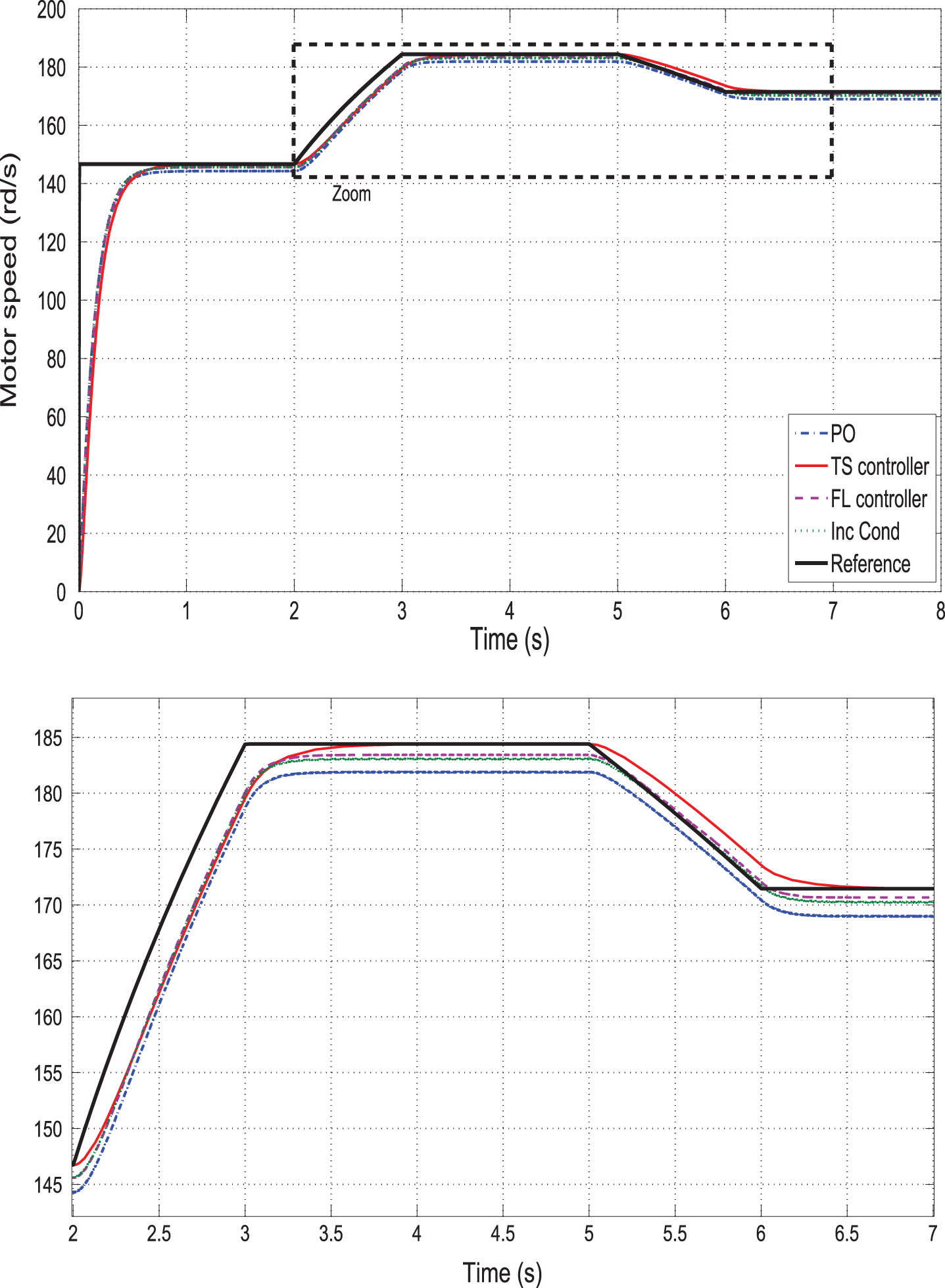
Motor speed and its zoomed curve.
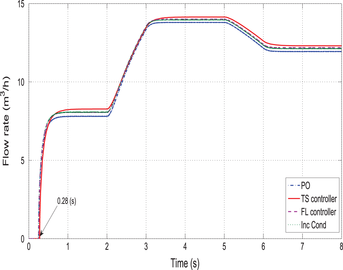
Flow rate of the photovoltaic pumping system at a constant static head Hg = 7.4 m.
By adopting the insolation level model given by Equation (26) and using the numerical integration given by Equation (27), a comparative study relative to the average motor output power, average hydraulic power and total daily pumped water are reported in Table 2. The proposed TS algorithm shows a higher motor-pump efficiency among all techniques. The maximization of the motor-pump efficiency leads to an increase of the flow-rate and therefore to a rise in the daily pumped water quantity. In addition, comparing the conventional MPPT techniques (P&O and Inc-cond) to the proposed fuzzy approaches (TS and FL), an apparent increase of about 2m3 of the daily pumping water amount is seen.
Comparison of different MPPT methods
Figure 10 illustrates the global efficiency of the PV pumping system (PV generator, DC converter and motor-pump) as a function of Q at a constant static head. It’s the ratio of the hydraulic centrifugal pump power to the input incidental power captured by the photovoltaic generator. It is obvious that the TS fuzzy controller owns a higher global PV efficiency among all presented techniques, thus ηmax achieves a value of 4.25%, where the motor-pump delivers 10.7m3/h at a pumping head of 8.05 m.

Global efficiency as a function of the flow rate Q at a constant static head Hg = 7.4 m.
In this paper a T-S fuzzy MPPT control method for a photovoltaic water pumping system driven by a DC motor was presented. Using the proposed MPPT fuzzy controller, it is easy to force the PV pumping system to operate close to the MPP trajectory by adjusting the motor speed at a reference value which has already been pre-calculated. The dynamic performance of the DC-motor pump with an intermediate boost converter use is analyzed under different levels of solar insolation. The controller gains are obtained by solving a set of LMIs and its robustness performance is further analyzed. The obtained simulation results show that the TS fuzzy approach exhibits a better tracking performance compared to the FL approach, and to the conventional P&O and Ind-cond algorithms. This leads to improve the efficiency of the PV pumping system and then to increase the daily pumping water amount.