
Abstract
Remarkable resource management and energy efficiency improvements can be achieved in greenhouses using innovative technological advancements and modern agricultural methods. Deployment of Internet of Things (IoT) and optimization algorithms in greenhouse farming is highly desirable for real-time monitoring and controlling various parameters with optimal solutions. However, IoT based greenhouses require more energy as compared to traditional farming. This paper proposes an optimal greenhouse water supplement mechanism with efficient energy consumption based on IoT and optimization techniques. The first contribution of this study is to gather the actual water and soil moisture levels from the greenhouse and tank using IoT devices. Secondly, the formulation and deployment of an objective function to compute the optimal water and soil moisture levels for greenhouse and tank based on user-desired settings, the system constraints and actual sensing values. We applied a rule-based expert system to activate water pumps with the required flow rate and operational duration to achieve efficient energy consumption. To prove the effectiveness of the proposed concept, embedded IoT devices and objective function for optimization are deployed as well as, a number of experiments are conducted to provide the optimal water and soil moisture levels in a real greenhouse and water tank environment.
Keywords
Introduction
According to the United Nations report, the current world population of 7.6 billion is predicted to reach 8.6 billion in 2030 and 9.8 billion in 2050 years [1]. As the world population is continually rising, requirements for food and water products will also increase. Around seventy per cent of the surface of the earth is surrounded by ice caps, oceans, lakes, rivers and other water resources. However, only 0.3 per cent is of these water sources is acceptable to consume. The remaining 99.7%of water is salty and can not be consumed [2]. Water resource plays a vital role to develop sustainable food production techniques because humanity is not able to produce agricultural products without appropriate irrigation. As the number of agricultural lands is increasing continuously, the water resource is also decreasing. More than 70%of the world’s population is now living in urban areas, and nearly half of the world population is supposed to live in water-stressed places by 2025 [3]. The United Nations reports that around 1.8 billion people worldwide are likely to survive in areas of absolute freshwater shortages [4].
Several reasons have been influencing water resource usage and food production such as climate change, global warming, population growth, water wastage, and to name a few [4]. Therefore, institutions, researchers, international organizations, societies, and individuals need to combine new technological advancements to the food production and water industry for creating various alternative pathways and scenarios to overcome food and water-related issues. One of the highlighted examples among these solutions is greenhouse technology. The greenhouse is one of the greatest inventions in human history, which can solve both water-conserving and food production problems [5]. In recent years, the greenhouse industry is becoming more and more productive and has experienced significant growth [6]. However, the development of healthy crop production in a greenhouse requires effective management of environmental factors such as temperature, humidity, water level, soil moisture, carbon dioxide and so on [7].
Deployment of Internet of Things devices to the greenhouse environment can bring extensive opportunities to modernize and automation of the crop production process. Over the last few decades, we have been witnessing the extensive utilization of IoT technologies and smart applications in various industries. Among these various IoT based industries, we can find smart greenhouses, smart transportation, smart grids, smart factories, smart home automation, smart farming and so on [8–11]. McKinsey Global Institute estimations illustrate that by 2025, the Internet of Things (IoT) will contribute approximately $3.7 trillion to the world economies, and $140 billion to the IoT-based agriculture and water industry production [12, 13]. These estimations present that IoT will be one of the leading players in the agriculture and water industry.
The development of various types of IoT based greenhouse management technologies enables precise control over environmental data, thus allowing optimal and efficient management of natural resources [14]. However, IoT applications require the deployment of various technological devices such as sensors, actuators, microcontrollers, and to name a few. As the number of devices increases in the greenhouse, energy consumption also becomes remarkably high. Because energy is one of the foremost resources in today’s world, and the cost of energy is increasing day by day. Due to that, researchers and scientists have been trying to minimize energy consumption and optimize crop production in greenhouses by applying optimization algorithms [15].
In this work, we proposed the greenhouse attached water tank concept to control water resource in the greenhouse. Attached water tanks are one of the widely used solutions to maintain sustainable water continuously to the greenhouse. One of the main problems in the greenhouse and water tanks is water wastage, which occurs as a result of overwatering the plants and overfilling the water tanks [16]. Conventionally, water supplements for both greenhouses and tanks are controlled manually by operators. If the operator is absent or leaves the workplace, water overflows from the tank, the water pump consumes an unintended amount of energy, and it affects the plant growth negatively.
To this end, this paper presents an optimization assisted automated water management system for the IoT based greenhouse and water storage tanks using embedded devices and an objective function. The contribution of this paper involves the following 4 phases: Firstly, the deployment of sensors and actuators for the greenhouse and water tank environment to collect the environment parameters. Secondly, the implementation of the IoT based data acquisition unit to the proposed system to collect the real-time soil moisture and water level sensing values. Thirdly, applying a novel objective function to calculate optimal soil moisture and water level to the environment based on actual sensing values, user-desired settings, and constraints. Lastly, the development of a rule-based control module that computes the flow rate and operational duration for water pump actuators with efficient energy consumption.
The rest of the paper is organized as follows. Section 2 introduces related works regarding water supplement approaches based on IoT and optimization. Section 3 describes the proposed system design with a detailed formulation of the optimization scheme and control scheme. The experimental environment of the proposed system is described in Section 4. Section 5 outlines the performance evaluation results. Conclusion and future work is presented in Section 6.
Related works
In recent years, technological researches and developments have been helping to produce a new type of technologies and skills that provide us to make more improvements in the greenhouse industry. The water source is one of the most crucial aspects of effective crop production in several areas, where finding adequate water for plant watering is challenging because of various external and internal factors [17]. One of the highlighted technologies for water management is the Internet of Things (IoT) concept. The IoT is a network of embedded devices, intelligent computers, and various objects which can share and collect massive amounts of data for automation and control of the environment in smart homes, smart cars, smart cities, and many industries [18]. The IoT is revolutionizing manufacture in industries by enabling more faster and more efficient data acquisition and accessibility processes [19]. Continuous monitoring of greenhouses and water storage tanks offers reliable information and data to help experts’ better knowledge and understanding about how each factor influences water management and how to increase plant production. Suppose greenhouse and water tanks are equipped with IoT sensors and actuators. In that case, the actual measurement of the water can be sent to the server with regular intervals for managing effectively the water filling process [20].
Kodali [21] developed a smart greenhouse irrigation system with an attached water storage tank. That proposed system included humidity, temperature sensors, and a fogger actuator. Required water obtained from any sources such as rainwater harvesting, canal tube, firstly stored in the water tank. An ultrasonic sensor installed to the water tank, which monitored the water level continuously and sent notifications to the user as soon as the water level decreased from the requirement. The microprocessor was used for the activation or deactivation of a water pump according to the water level. Their proposed approach decreased water consumption by 70–80%.
Prieyen et al. [22] introduced an IoT based smart water tank system control using an android application. Their proposed system included three central units, namely, sensing unit, control unit, and motor unit. They developed a simple rule to their system for controlling the motor if the current water level was below minimum level motor was activated until the water level reached the maximum level. In contrast, if the current water level was equal to the maximum level, the motor was deactivated. ESP8266 and an ultrasonic sensor were utilized as microcontrollers and sensors, respectively.
Narrow Band Internet of Things (NB-IoT) based remote water level monitoring system for industrial water storage tanks were suggested by [23]. The authors used two different sensors for sending alarm (Magnetic switch sensor) and checking water level (Floating sensor arrangement) for their proposed approach. Magnetic switch sensors installed with buoyant objects to the bottom and the top parts of the water tank. According to the water level, buoyant objects moved and magnetic switch influenced on the alarm and water level (in peak point or basement) were sent to the system. Alarm and LED actuators activated automatically at the same time when the current water level was below or above the desired ranges.
The study [24] presents LabVIEW and Arduino based on a non-contact water level monitoring system for water storage tanks. An ultrasonic sensor measures the water depth from the tank, according to the actual water level LabVIEW application sends the data to the Arduino board, then the water pump is activated or deactivated automatically through the Arduino. The current water level data of the tank is visualized on the graphical user interface, which is provided by LabVIEW.
Shankar et al. suggested a smart water level control system for regulating water wastage for tanks [25]. Their proposed system overcomes water wastage in water tanks based on an IoT and mobile application; more precisely, this system detects overflow of the overhead water tank and sends a notification to the user. The user can turn on or turn off the water pump through the mobile application.
Fisher and Moore [26] developed a continuous optimization solution for water control valves based on pump pressure in different set-points. This system helps to minimize the pump energy consumption by keeping open one control valve nearly all times. Their control method is simple and does not require more hardware than a conventional control method. Each air handling scheme monitors chilled water to provide the discharge setpoint of the air temperature. The pump’s speed is controlled by the variable frequency drive in differential pressure. There was a 44%reduction in power consumption in the utilization of the new differential pressure reset program.
Braun et al. [27] introduced the optimum controlling settings for water supplement systems without using storage; this system was based on optimization and system-based controlling. Chilled water loop supplement and the return temperature difference was also thought to influence on the pump power and chiller loading. Their proposed ChW system was developed, and three variables were chosen for the optimization case. Optimization is 3.3%effective compared to the baseline in annual cost saving.
Zhuhong Zhang [28] developed a multi-objective optimization algorithm for dynamics environments that aims to control the greenhouse environment. His research topic aims how to build dynamic multi-objective optimization immune algorithms to recognize and adapt to environmental monitoring and improving. For greenhouse control, they created a decision rule for controlling based on MOIA (Multi-Objective Immune Algorithm). The author mainly paid attention to the algorithm side of the system; however, this work does not consider IoT devices and their role in the greenhouse.
The literature shows that the highest percentage of the existing studies are paid attention to remote monitoring greenhouses and water tanks with sending alarms, reminders, and notifications through IoT devices, these notifications help to improve working effectiveness. Their main target is to check the water storage condition remotely when required [21–25], and based on forwarded information controlling the actuators manually. According to our limited knowledge, there is no related literature for the optimization of water management in both greenhouse and water tank based on the IoT and optimization algorithms. However, our proposed approach represents the combination of IoT devices and a novel objective function for the optimization and automated control of the water source in greenhouse and water tank with efficient energy consumption. Rule-based systems are the primary form of Artificial Intelligence, which is known as an expert system or production system [29]. Expert systems are created to find solutions to various complex problems using the knowledge which are described with rules rather than traditional hard coding. A rule-based system is based on specific rules as the knowledge representation for finding the solution to the intensive knowledge problem. The rule-based system includes “If-Then” rules, which controls the application based on specific rules and set of facts. Each rule analyses a relation, strategy, recommendation, or heuristic. Rule-based systems are easy for adaptation and understanding, and simple model for solving complex problems in a faster way [30].
Proposed system architecture
In this section of the paper, we describe the design of the proposed mechanism with a detailed formulation of the objective function. The proposed system conceptual architecture is described in Fig. 1. We have a greenhouse environment that includes the greenhouse, the water tank, two water pumps, soil moisture sensors (M1, M2, M3, and Mn), water supply pipes for drip irrigation, and water supply to the water tank. The entire process includes three major phases. Firstly, the actual soil moisture and water levels of the greenhouse and the water tank are monitored by the sensors, and sensing data is collected to the data acquisition module. Secondly, an objective function computes the optimal water and soil moisture levels according to the actual environmental values, user/farmer desired settings and system constraints. Thirdly, the rule-based control module computes the flow rate and operational duration limits to the water pump for attaining the required water quantity with efficient energy consumption. Required water is provided to the water tank and the greenhouse through the pump 1 and the pump 2, respectively. Whenever water and soil moisture levels decrease in the water tank and greenhouse, respectively, sensors sense the change and sends actual water level data to the system. According to sensing data, the optimization scheme calculates the optimal water and soil moisture levels based on the actual sensing values, user-desired settings and the system constraints with efficient energy consumption. Based on the actual and optimized sensing values rule-based control module activates or deactivates the water pumps and increases the soil moisture and water level automatically. When the actual environmental parameters are at optimal ranges, the water pumps are switched off without human intervention.
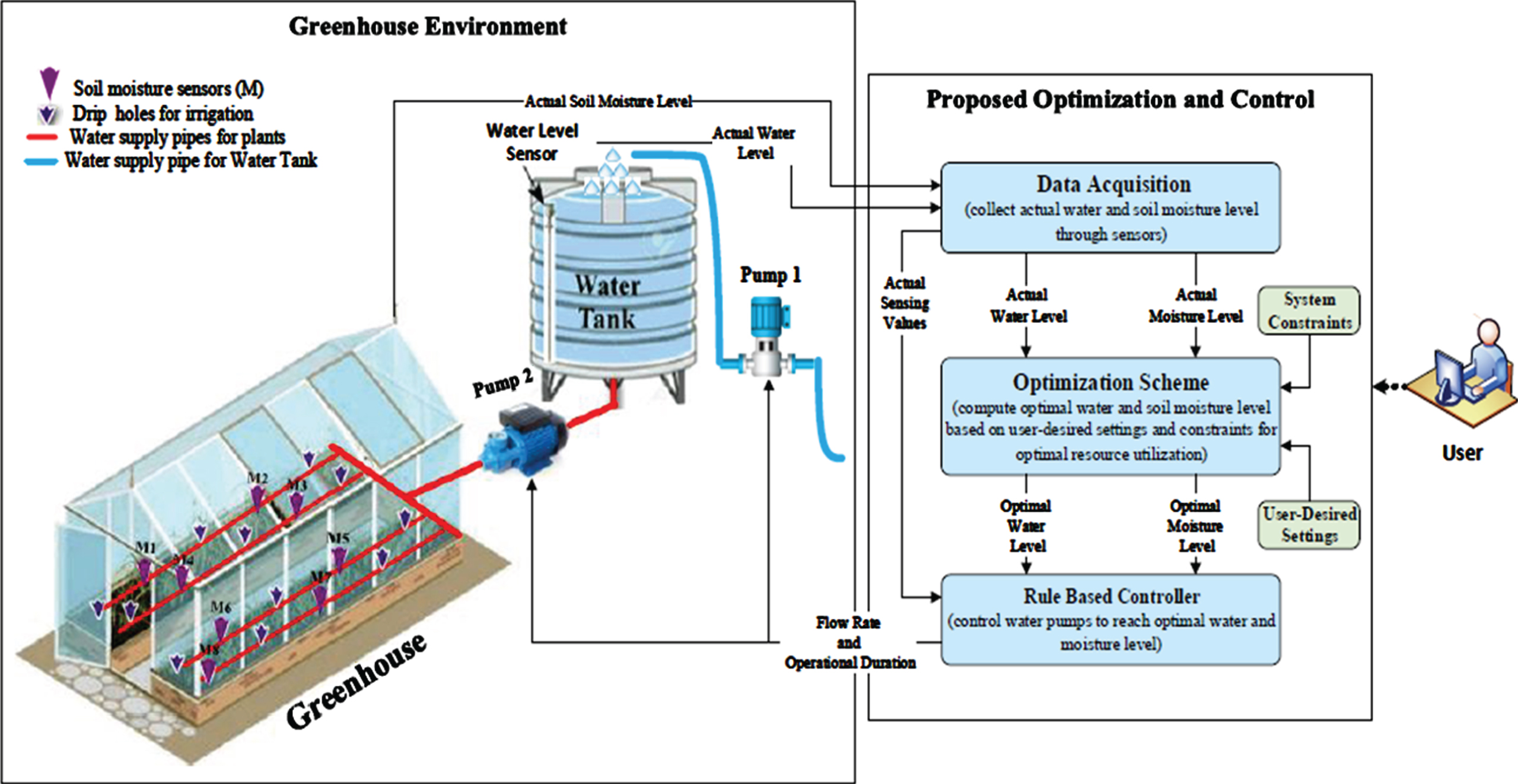
Proposed conceptual design for IoT based water storage tank.
There are several types of irrigation systems and techniques are available for greenhouse watering. Usually, farmers use media surface tapes, drip tubes, by hand using a hose, sprinklers, and to name a few [31]. The main aim of these techniques is to save water, labour, and decrease groundwater pollution. We used the drip irrigation method, which is one of the essential irrigation methods for the development of a perfect growing environment and water usage in the greenhouse [32]. The water supply pipe is connected between the greenhouse and the water tank through water pump 2, and also water supply pipes are installed to every line of plants. Every line of pipes has special holes for water drips.
Figure 2 illustrates the flow chart diagram of the proposed approach. The process starts with reading the actual water and soil moisture values from the environment using sensors Afterwards, in the optimization process, if any sensing value is outside the user-preferred ranges, then optimization is applied. In our proposed approach, we consider the optimization in two schemes-baseline scheme and optimization scheme; The baseline scheme is based on user-desired ranges and does not require a complex mathematical calculation. The other scheme is an objective function based optimization scheme which we developed for the calculation of the optimal water and soil moisture levels according to the constraints and user/farmer desired settings. Finally, the actual sensing and optimized sensing values are passed and analyzed in a rule-based control module. The rule-based control module sets flow rate and operational duration to the respective pumps with efficient energy usage. We have developed a C# based desktop application which has an internal database to store sensing and optimized parameters for future analysis. Users also can insert their desired minimum and maximum ranges for water and soil moisture levels using the application interface.

Flowchart diagram for Proposed Approach.
In this section of the paper, we describe our proposed objective function formulation for optimization in detail. An optimization algorithm is a procedure which is activated iteratively by comparing existing solutions until an optimum, or a satisfactory solution is found. Optimization algorithms have been widely used in various areas for minimizing the production cost or maximizing the profit [33, 34]. The objective function is the basement of optimization algorithms, which is formulated for finding the optimal solution for a specific domain [35]. Real-world problems consist of multiple objectives, and the overall system requires to be optimized simultaneously [36, 37] using multi-objective optimization. Multi-objective optimization based applications have been applied in many areas, such as engineering, agriculture, logistics, economics, and to name a few [38–40]. We have formulated the multi-objective optimization algorithm for keeping the water and moisture level at an optimal level in order to achieve optimal resource utilization by avoiding overfilling the tank and overwatering the greenhouse. However, the proposed objective function can be applied to the other environmental parameters such as temperature, humidity, pH, and CO2 level. Let us assume greenhouse (G) and water tank (T) actual parameter readings which are given as
W
a
depicts actual water level, while actual moisture level is considered as M
a
. As can be seen from Fig. 1 that, there can be several soil moisture sensors in different locations of the greenhouse because it is difficult to decide actual moisture values based on one or two moisture sensors in the complex greenhouse. Various moisture sensors in the greenhouse environment are labeled as Ma1, Ma2,Ma3, … MaN. Our target is improving the overall condition of the greenhouse and water storage environment, so we calculate the average actual soil moisture level (M
A
) and the average water level (W
A
) according to the different sensor nodes’ actual values with the following equation. In our proposed system, there is only one water level sensor so it can be assigned as W
A
= W
a
Where K describes the number of sensors that are used for measuring the actual soil moisture level. Through the equation mentioned above (2) the average actual sensing values (GTP A ) can be calculated for each sensing values. The list of symbols used in this formulation is provided in Table 1.
Summary of Symbols and Notations
User/Farmer can select the most desirable values for both parameters as
Let W
min
, M
min
and W
max
, M
max
denote the most acceptable the min and the max user-desired ranges for the water and soil moisture levels, which can be selected by the user/farmer according to the greenhouse and water tank condition.
The max value describes a highly desirable point for water and soil moisture, and the min value is the least desirable points. If there were not any problems with energy cost, the user would obviously want to set the maximum point for parameters to boom the production. For the compactness, the range length of the minimum and the maximum parameters described as
Suppose that the following equation determines the optimal setting for a compromise between the desired environmental parameters and energy consumption:
Optimal water and soil moisture levels come between the minimum and the maximum user-desired parameters as described in Equation 7,
The total consumed energy for maintaining optimal parameters for the water, and soil moisture levels are described as follows
Where E
W
o
, E
M
o
present consumed energy with optimal environmental parameters, which is calculated with the below-given equation.
Where Pwp1 and Pwp2 show the consumed energy by the water tank pump and the greenhouse water pump, per unit change in water level. Above is the total required power for maintaining optimal energy settings for water supply. We can assume the possible minimum and maximum power consumption as below
Where
It is clear that user/farmer aims to achive a highly productive greenhouse environment with less energy utilization. G
p
and G
e
present the gain for optimal environmental settings and energy consumption, respectively. User preferences are described with α
p
and α
e
, if the user wants to give more attention to optimal water level and soil moisture parameters, then the user needs to give more weights to the α
p
. If the user aims to increase energy efficiency, then more weight is needed to α
e
values, as formulated in Equation 12. These desired α
p
and α
e
objective weights are given in the range [0, 1]. If the user pays more attention to the optimization of energy consumption, then he or she can give 0.9 value for the α
e
, and 0.1 value for the environmental parameter weight. If the energy consumption is not a problem for the user, then the user can boost the production by giving high weight to the optimal environment (α
e
= 0 and α
p
= 1). In this work, we consider the objective weights for the optimal environment and energy consumption as an equal by assigning them α
p
= 0.5 and α
e
= 0.5 values.
D
M
and D
W
illustrate the deficiency for attaining the optimal values for the soil moisture and water levels. Assigned weights for the water level and soil moisture are described with w
W
and w
M
, respectively. According to its significance for crop production such that w
W
+ w
M
= 1. In order to increase the gain for the development of the optimal desired environment G
p
, the deficiency component of each defined parameter must be minimized by using the below-given equation.
To set up optimal water and soil moisture levels to the tank and greenhouse, deficiency component D
X
is needed to be minimized. If W
A
< W
min
then desired optimal environmental parameters are needed to fix W
o
≈ W
max
. If W
o
→ W
max
then D
W
→ 0 which is likely to support in increasing the desired G
p
. The energy consumption gain (G
e
) can be computed with Equation 14,
For maximizing energy efficiency, the minimization of energy utilization is needed E opt . When E opt → E min then G e → 1 that supports the maximization of the energy-efficiency G e . Therefore, the final objective function for optimization becomes
Constraints:
As we mentioned in Section 2, the rule-based system aims to gain knowledge from a human expert and convert this into a number of hardcoded rules to apply to the input values. The widely used basic form of the rule-based system is conditional statements such as if A, then do X, else if B, then do Y. Rule-based systems can be easily adapted and acceptable for some various problems [41]. Using a rule-based system is dependent on the problem area. If the problem area is not remarkably too broad if-then rule statements are appropriate, wide problem area requires too many if-then rules., As a consequence, the system might face some difficulties for calculating and it influences on decreasing performance speed [42]. In our proposed approach, we applied the rule-based control model for computing the optimal water and soil moisture levels comparing with actual sensing data and optimized data. Control module sets flow rate and operational duration for water pumps; Fig. 3 describes an abstract diagram of a rule-based controller; we have input parameters, rule-based controller and output.
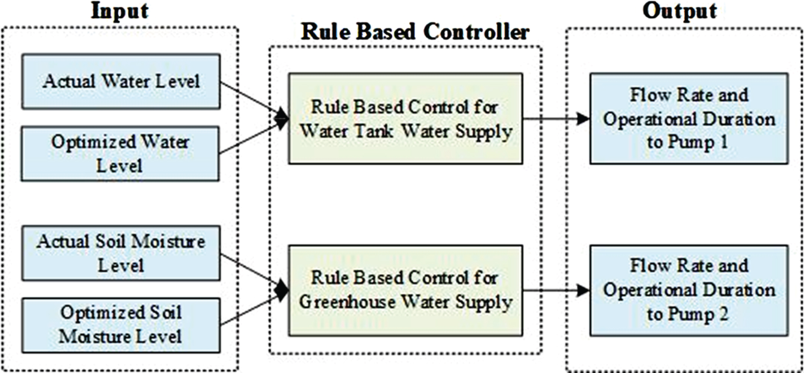
Rule-based control system conceptual diagram for water supplement.
There are four input parameters to the rule-based controller, namely actual sensing and optimized values for the water and soil moisture level, and the rule-based controller sets the flow rate and operational duration for each water pump. Figure 4 illustrates the detailed flow diagram of the proposed rule-based control module. It can be seen that there are two possible cases for the water supplement to the tank through the water pump 1. The first case is when the actual average water level (W A ) is greater than or equal to the optimal water level (W o ), then activation is not needed to the water pump actuator. The other case is when the first case fails, and the actual average water level is lower than the optimal water level, then the activation is needed to the water pump. Water pumps’ operational duration (dur) and flow rate (rate) set according to the difference between the actual average and optimal water levels. For the finding flow rate and operational duration, we developed W and M related formula. As can be seen, when we divide into five the multiplication of the water pump operational duration and water pump flow rate, the results need to be higher than W. The same applies to the optimization of the soil moisture level in the greenhouse using water pump 2. If the average soil moisture is greater than or equal to the optimized soil moisture level, then water pump 2 is not activated. Whenever the actual soil moisture level is less than optimal level, then the M is used to calculate the water pump’s flow rate and operation duration to activate the pump.
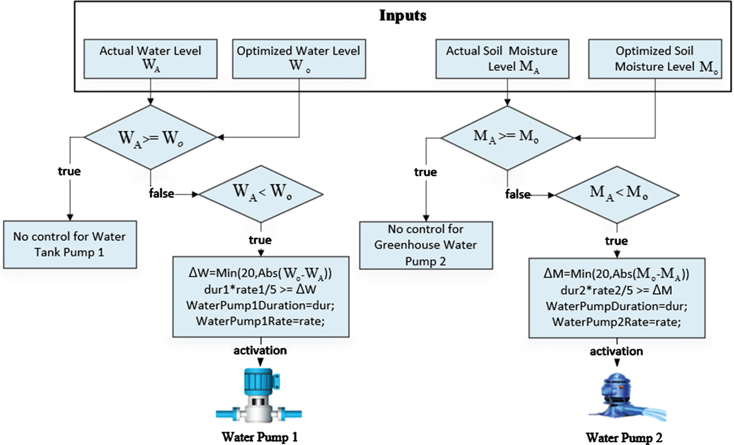
Flow diagram of a rule-based control module.
Figure 5 describes the operational sequence diagram of the proposed water supplement system to the greenhouse and water tank. The user can run the optimization and control module from the user interface. Water level and soil moisture sensors monitor the environment continuously, and sensing data is collected in the data acquisition unit. An objective function based optimization module calculates the optimal soil moisture and water level for the greenhouse and water tank, respectively. Optimized data is sent to the rule-based control module. The rule-based control module sets the required flow rate and operational duration to the water pumps according to comparisons between optimized values and actual sensing values. The power source describes the energy requirement for water pumps (measured in watts). According to the water pumps’ activation unit, the total consumed energy can be calculated using the pumps’ flow rate and operational duration. It is clear that, if the water pumps are activated with a minimum flow rate, then they require less energy and more time to increase water or soil moisture levels. If the water pumps are activated with a maximum flow rate, then they spend more energy, but less time. By assigning an optimal flow rate and operational duration to the water pumps ’ efficient energy consumption can be achievable.
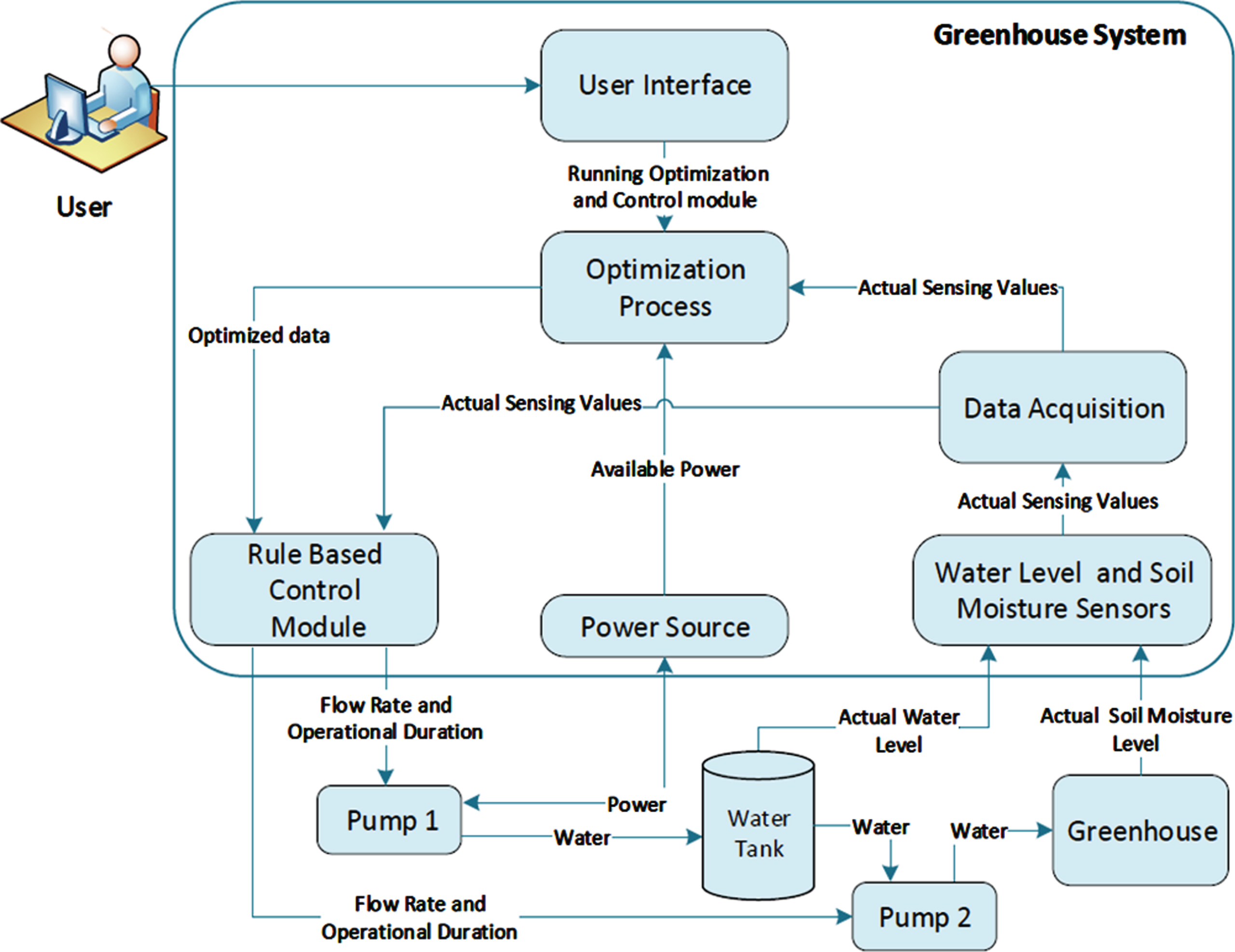
Operational sequence diagram of the proposed approach.
For the assessment of the proposed concept, an indoor greenhouse and water tank environment were designed as a real experimental environment. The experiment was conducted in the Internet of Things and Mobile Computing Laboratory; the room number was D423 in Engineering Building 4 at Jeju National University, Jeju-si, South Korea, between October 2019 and November 2019. Figure 6 represents the experimental environment of the greenhouse and water storage environment. The water level sensor and water pump 1 were installed in the water tank. The water level sensor was used to collect the actual water level from the water tank, as the level of the water decreased from the optimal range water pump 1 was activated automatically to increase the actual water level to the optimal point. As can be seen, water pump 1 had two water pipe connections, one provided water from the external source, while the other was installed to supply water to the water tank. Because of the limited resources, we installed only 2 soil moisture sensors (Soil moisture 1 and soil moisture 2) to the greenhouse from two different locations to measure the actual soil moisture values. However, the proposed system can be extended with more sensors to detect the soil moisture levels from various locations of the greenhouse. The second water pump (labelled as pump 2) was installed to the inside of the tank to provide water to the greenhouse through the water pipeline. Installed water pipeline to the greenhouse had special drip holes, which supported drip irrigation to the greenhouse lines. Arduino was used as the IoT gateway, which supported the connection between embedded devices and the server.

Greenhouse and Water tank experimental environment.
Table 2 presents the used IoT devices and their descriptions for the development of the proposed water supplement system experimental environment.
Deployed IoT devices and their description
We developed a C# based water supplement system application to monitor and control the greenhouse and water tank. Figure 7 describes the main simulation interface window. It can be seen that before running the simulation process, the application requires some settings and connections. Users can connect and disconnect the sensors and actuators. The most acceptable maximum (W max , M max ) and minimum (W min , M min ) user desired ranges for each parameter can be inserted from the application interface. These ranges are used to compute the optimal soil moisture and water to the greenhouse and water tank, as formulated in Section 3.1 equation 3. For the visualization of the results, we have two sub-windows: Greenhouse and Water Tank. Each sub-window includes optimization module results, control module results, and energy consumption results. According to the water pumps’ flow rate and operational duration, energy consumption results can be calculated automatically and can be seen from the energy consumption results’ tab page.

Greenhouse Water Storage Tank Application interface.
We have two types of optimization, the baseline scheme is based on user desired settings. The other one is based on an objective function-based optimization, which we developed for optimizing actual sensing values to the optimal values with efficient energy consumption. In the control module, if the user clicks start button water pumps’ flow rate and operational duration results for both greenhouse and water tank.
Table 3 depicts the used technologies for the implementation environment of the proposed system.
Description of the used technologies for the development of the proposed system
This section represents a detailed discussion of the proposed system experimental results. These results are divided into four parts to improve clarity. In the first section, the IoT based data acquisition unit and actual sensing values are described with user desired set points. The second part shows the optimization module results, whereas the control module results are given in part 3. Eventually, energy consumption results are presented to assess the effectiveness of the proposed novel objective function.
Deployment of IoT based data acquisition unit
For the IoT based data acquisition, optimization, and control modules, we developed the Apache HTTP based server, and sensing values from the environment can be stored to the MySQL database using an HTTP POST request, as shown in Fig. 8. Collected soil moisture (M1, M2) and water level (W) sensing values were saved to the database, and these values were described the system interface in visual charts. Collected data was uploaded to calculate optimal soil moisture and water level values using the proposed objective function. According to the actual and optimized environmental values, the control module calculated the flow rate and operational duration for the water pumps; then, the proposed system sent On or Off commands to the IoT Gateway in the required time for the activation or deactivation of actuators. The measurement units for the soil moisture and water level values were considered in %and mm, respectively.

IoT based Data Acquisition Unit.
It is important to note that the farmer needs to pay attention to install the driplines to spread the same amount of water for each location through water pipelines. Pumping out various amounts of water to different locations is likely to decrease the effectiveness of the proposed system. Let us imagine one pipeline has more drip holes, and then the more water spreads to this crop line, the soil moisture sensor (M1) detects the actual soil moisture level as 90%. If in another greenhouse location, the water pipeline has fewer drip holes, then obviously the soil moisture level becomes less, such as the M2 sensor detects soil moisture as 10%. After that, the actual average moisture level is calculated as MA=(M1 + M2)/2, and the result becomes (90%+10%)/2 = 50%, according to Section 3.1 equation 2. It seems 50%of soil moisture level is enough for greenhouse crop production; however, different locations have various soil moisture levels, which can affect badly for greenhouse crop production.
Figure 9 describes the summary of the actual collected data values during October 2019 with the user desired minimum and maximum points. The X-axes describe 31 days of data collection period; however, the experiments were carried out using one month’s data in which water level and soil moisture sensors had collected this data every hour during the mentioned period. Figure 9(a) shows that minimum and maximum user-desired points were 60%and 80%, respectively. However, actual soil moisture levels were below the minimum user desired threshold in most of the days. If actual soil moisture levels come between user desired points, then we do not need to activate the greenhouse water pump to increase the soil moisture level. The same consideration also applies to the water level values in the water tank. The optimal water level for the tank is between 250 mm and 300 mm. The actual water level data fluctuated throughout the given period. On October 3, 7, and 29 data instances, the actual water level values were acceptable for the user required points. However, in some days, the water level data instances were below the user-desired values. Overwatering also can be seen in 13, 14, 23, and 25 October.
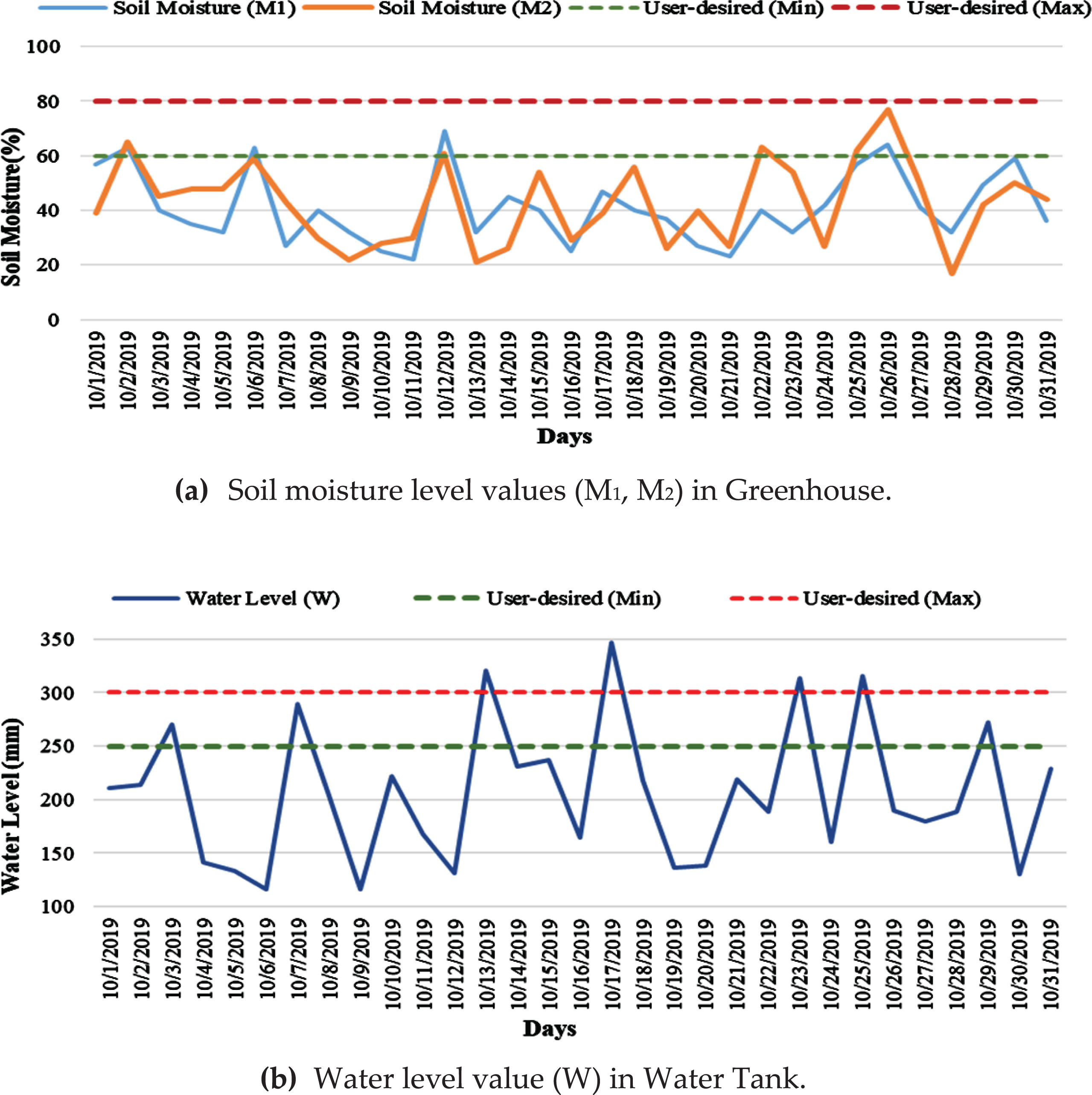
Actual data instances with user desired points during the month (October 2019).
The user/farmer knows which soil moisture and the water level are the most desired levels and which one is the least acceptable level for keeping the soil moisture and the water level at the optimal point. If the cost of energy power is not an issue, the user sets the maximum desired level and boost the production of the greenhouse. The setting of maximum parameters for the greenhouse is likely to require high energy consumption. For this reason, creating a stable condition between energy consumption and the environment is essential. For the model simplicity, visibility, and straightforward explanation, the optimization module results were described using 150 data instances, as presented in Fig. 10. Actual soil moisture and water level lines show that only some points are acceptable for user desired settings, and other sensing values are outside of the user proposed ranges.
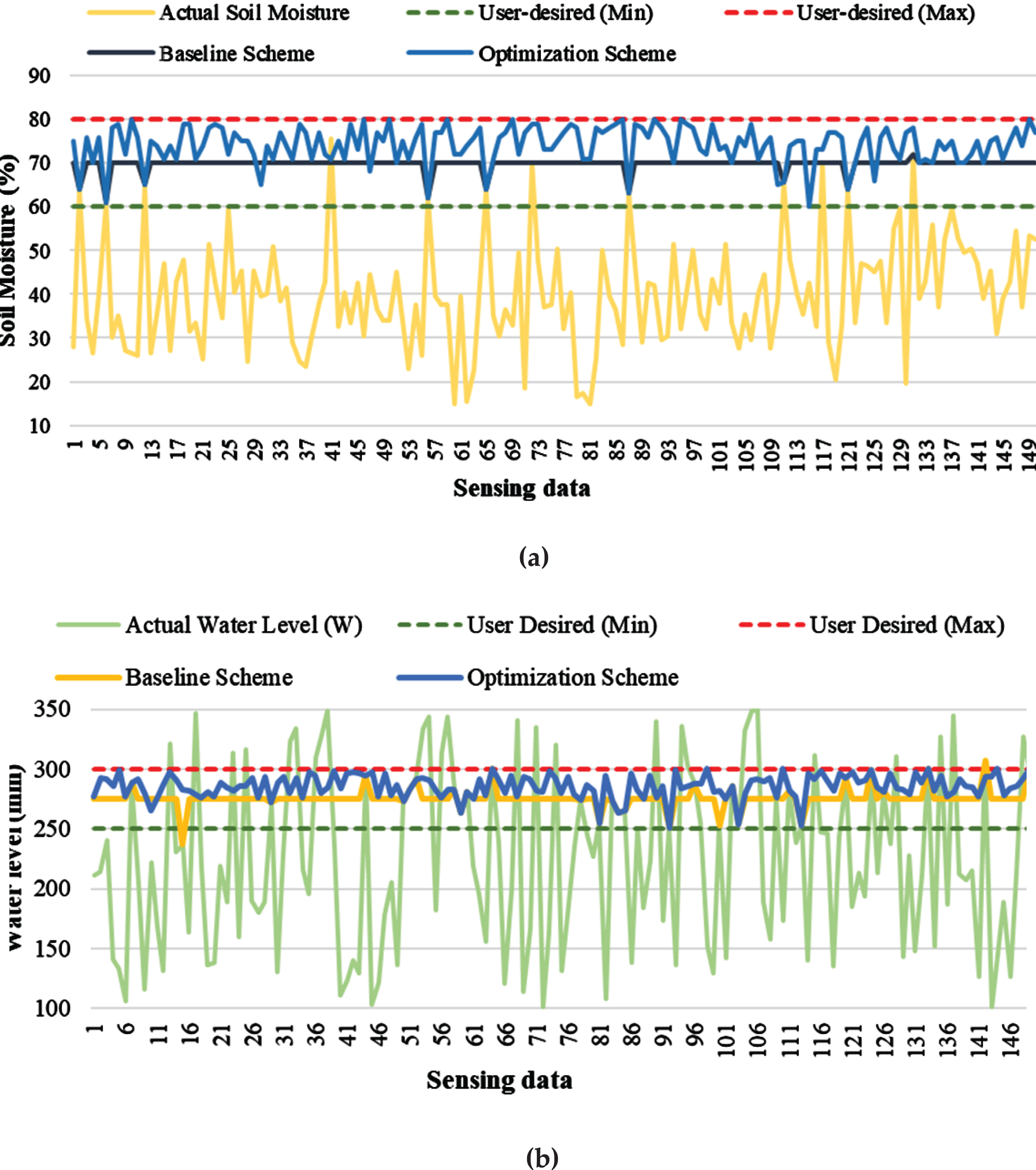
Optimization module results. (a) Soil moisture level optimization for greenhouse (b) Water level optimization for water tank.
For the sake of comparison of the effectiveness of the proposed objective function, we considered a baseline approach for improving the water and soil moisture levels. The baseline scheme does not include optimization formulations and selects the midpoint of the user-specified range for each parameter if the actual sensing values are outside of the user desired ranges, as shown in Equation 17,
If the actual soil moisture and water levels are equal to 30%and 120 mm, respectively, then the baseline scheme results become ((60%+80%)/2)=70%and ((250 mm+300 mm)/2)=275 mm. The baseline scheme is relatively simple, the actual sensing values are continuously monitored using sensors. As the sensing values are outside of user-desired set points, then the water pump actuators are operated automatically until the water and moisture levels reach the midpoint of user-desired ranges. When the user clicks the baseline scheme button from the application, the system calculates the baseline scheme-based optimization results. The formulated objective function for the optimization scheme calculates the optimal soil moisture and water levels for the greenhouse and water tank according to the sensing data. Optimization scheme results represent that optimized sensing values always came inside of the user desired minimum and maximum values. Furthermore, the optimization scheme based results were more optimal comparing with baseline scheme results.
In this section, we discussed the rule-based control module results of the water pumps. According to the flow rate, water pumps are divided into single and variable flow rate pumps. A single-flow rate pump activates at one fixed rate, and a variable flow rate pump can be programmed to run at many different rates [43]. A high flow rate consumes more energy in comparison with the less pumping rate. On the other hand, it is favourable to run a water pump at a higher flow rate to fill the water tank in a short time. In the greenhouse and water tank environments, the quantity of the required energy of the pump activation can be decreased by changing the water pump flow rate, but it demands to activate the pump for additional time, more precisely, if the pump needs to be activated with the flow rate of 60 ft3/min for 8 hours in a day, then operating the same pump with 30 ft3/min requires 16 h of activation in one day. For rule-based control setup analysis, we considered three variable flow rates, namely, minimum, average, and maximum flow rates. Table 4 describes the required energy consumption and operational duration for each pump according to the water pumps’ flow rates. As can be seen, if the water tank pump is activated with a minimum flow rate, then it spends less energy (600–1000 watts) but more time (600–1000 minutes) to increase the actual water level to the optimal level in the tank. If the greenhouse pump is activated with a maximum flow rate, then it requires more energy consumption (210–300) with less operational duration (5–10 minutes) to provide an optimal moisture level to the greenhouse crops.
Energy consumption and operational duration ratings for each flow rate
Energy consumption and operational duration ratings for each flow rate
The rule-based controller module is used to control the operation of water pumps based on optimized parameter values and actual sensing values. When the actual sensing values are lower than minimum desired settings in per minute, the optimization scheme calculates the optimal parameter values for this sensing values and sends these levels to the rule-based control module. The rule-based control module selects the flow rate and operational duration for the water pumps based on actual and optimal sensing values. The water pump is activated automatically until the actual water level reaches the optimal point. If the current water level reaches the optimal level, then the water pump is deactivated. Section 3.2 includes a detailed explanation of the rule-based control module.
Figure 11(a) and (b) describes pumps’ flow rate and operational duration results in the greenhouse and water storage environments, respectively. The water pump actuator was activated in three flow rates, namely minimum, average, and maximum, to increase the actual soil moisture and water level sensing data in both the greenhouse and water tank. As we mentioned above, the soil moisture level of the greenhouse was measured in percentage, and the water level of the tank was considered in mm. As expected, the activation of water pumps with various flow rates required a different operational duration to increase the actual environmental sensing values to the optimal parameters. For example, the greenhouse water pump operational duration was 15, 13.6, and 5.7 minutes based on minimum, average, and maximum flow rates, respectively, between 1 and 5 sensing values. The actual soil moisture levels were below than user-desired minimum range in most of the time, whereas, actual water levels of the tank were between the user desired minimum and maximum ranges. As a result, the greenhouse pump required a more activation period compared with the water tank pump.

Rule-based control module results: (a) Greenhouse water pump (b) Tank water pump.
According to the water pumps’ flow rate and operational duration results, we were able to compute the overall activation period for each water pump, as described in Table 5. Overall operational duration results are different based on minimum, average, and maximum flow rates. To optimize the actual soil moisture level, the greenhouse water pump required 1900, 1401.7, and 887.5 minutes with the minimum, average, and maximum flow rates, respectively. Whereas, activation durations were 1456.2 (minimum flow rate), 1084.6 (average flow rate), and 691.8 (maximum flow rate) minutes for running the water tank pump to provide an optimal water level to the tank based on actual water level.
Energy Consumption and operational duration ratings for each flow rate
There is a significant relationship between water pump flow rate and energy consumption. In order to conduct energy consumption analysis, we need to assign power ratings to the water pumps. As we already explained above, we utilized a variable flow rate water pump which can operate with different power consumption. Table 4 describes the required power ratings for the water pumps’ activation according to the various flow rates. If we take the greenhouse pump as an example, with the minimum, average, and maximum flow rate, the pump needs 75, 165, 255 watts, respectively. We could compute the consumed energy for each pump based on the overall operational duration results and flow rates. Figure 12 presents the quantity of the pumps’ consumed energy in kWh according to the various flow rates.
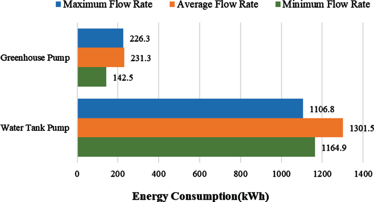
Actuators’ energy consumption results based on various flow rates.
It can be seen from the chart; the water tank pump spent more energy compared with the greenhouse pump due to the actuator activation requirement. The water tank pump consumed 1106.8, 1301.5, and 1164.9 kWh energy with maximum, average, and minimum flow rates, respectively. During the maximum flow rate activation period, the water tank pump spent the least energy. Average and minimum flow rate activation required more energy than the maximum flow rate. The greenhouse pump was spending 142.5, 231.3, and 226.3 kWh energy with the minimum, average, and maximum flow rates, respectively, to increase actual soil moisture level to the optimal in terms of 150 sensing data instances which were collected in every 30 minutes from the real greenhouse environment. Optimal energy consumption was achievable with activating the greenhouse pump with a minimum flow rate.
The IoT-driven water industry is an emerging concept that may potentially revolutionize water management in the greenhouse industry in terms of improving crop production, decreasing the water wastage. It offers effective resource utilization without human interference. With IoT, agriculture professionals can be able to control the water level in both greenhouse and tank simultaneously, and optimize the actual levels to the optimal parameters to boost greenhouse production with efficient energy consumption. To this end, this paper presents an optimization integrated IoT mechanism, where embedded devices were installed to the real greenhouse and tank environment to monitor actual soil moisture and water level values. The formulated objective function was utilized to calculate optimal soil moisture, and water level to the environment based on user-desired settings and the system constraints. Rule-based control module was applied to calculate and control water pump actuators with the required flow rate and operational duration to achive energy efficiency. The results section describes that an objective function-based optimization module could create a more desirable environment compared to the baseline scheme. Whereas, control module results show that controlling the greenhouse water pump with a minimum flow rate required 38%and 39%less energy compared to maximum and average flow rates, respectively. However, we need to activate the water tank pump with a maximum flow rate to decrease energy consumption to 15%and 11%compared to the other two flow rates. Future work will involve testing and development of the proposed system for real-world greenhouse and water tanks, as well as considering more environmental parameters and their control.
Author contributions
A.K., I.U., and D.H.K. conceived the idea, designed the overall system. A.K. designed the optimization scheme for the greenhouse and water tank, performed the experiments, and wrote the manuscript. I.U. assisted in model designing and experiments. D.H.K. proof-read the manuscript, and supervised the work. All authors contributed to this paper.
Conflicts of interest
The authors declare no conflict of interest.