
Abstract
This paper summarizes recent results of an exhaustive experimental study on possible uses of bent perfect crystal (BPC) slabs of Si employed in the fully asymmetric diffraction (FAD) geometry. In all cases the FAD-BPC slab is employed as the second crystal of the dispersive double-crystal setting in combination with another BPC slab. The FAD geometry was tested in the output beam expansion (OBE) as well as in the output beam compression (OBC) diffraction orientations. A comparison of dispersive parallel
Introduction
First publications on the diffraction properties of bent perfect crystal (BPC) slabs in the FAD geometry appeared in the nineteen eighties with the suggestion to use them mainly for one crystal neutron monochromators [5–7,9,11]. Special attention was paid to reflectivity properties of the FAD-BPC slabs [3,9]. However, practical exploitation of them for neutron scattering instrumentation can be found mainly in the next decade, namely, in the case of high-resolution SANS diffractometers [2,4,10,23,24], where the nondispersive
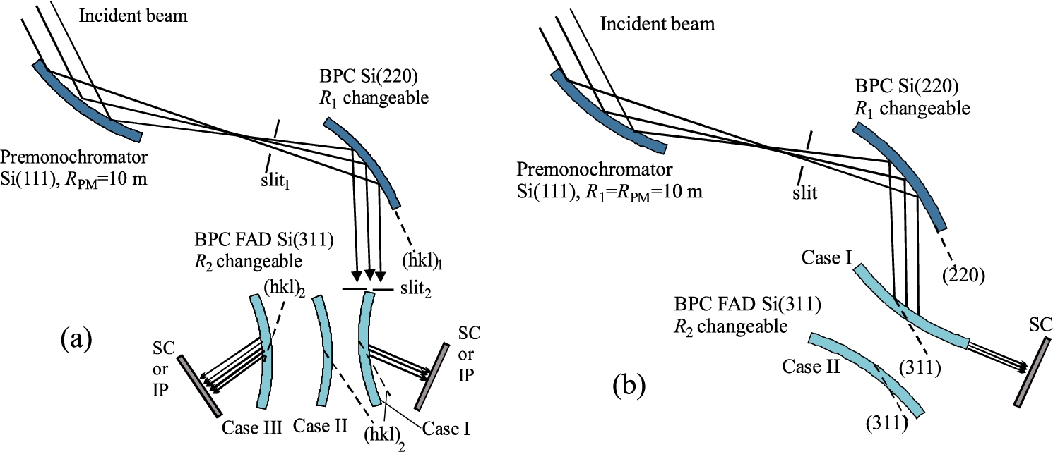
Schematic sketch of the experimental arrangements (a) and (b) as used for the studies of the properties of the double-crystal settings Si(220) + Si(311) with the Si(311) slab in the FAD-OBE and FAD-OBC diffraction geometry, respectively. SC – scintillation camera was at 50 cm and IP (Imaging plate) with the pixel dimension of 50 μm × 50 μm was at 40 cm from the FAD crystal.
Finally, the dispersive double-crystal Si(111) + Si(311) setting was used, where the former Si(111) premonochromator played an active role (as the first crystal) of the dispersive setting and made possible to free the third axis for installation of samples. Dimensions of all BPC Si slabs were: 200 × 40 × 4 mm (length × width × thickness). For cylindrical bending of the crystal slabs we used four-point bending devices [8].
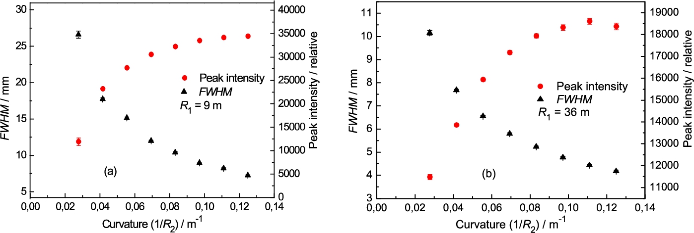
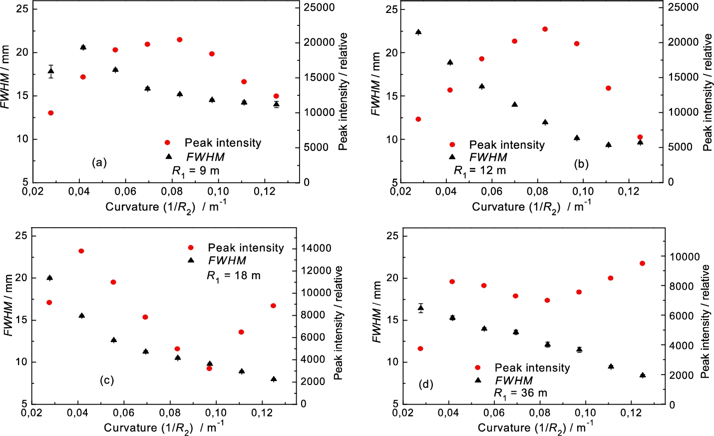
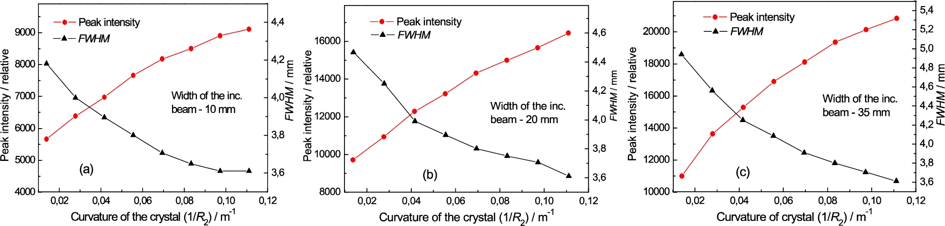
First, some properties of the FAD geometry (case I) related to the behaviour of the peak intensity and FWHM of the output diffraction profiles for different curvatures of the FAD crystal were studied. The obtained results are shown in the Fig. 2. It can be seen that in all cases of fixed curvatures on the bent Si(220) crystal slab, FWHM of the double diffracted beam profile decreases with the increase of the curvature of the FAD crystal. As the corresponding peak intensity of the profiles does not change considerably, it means that the change of FWHM is not given directly by focusing in real space but by the overlapping of the phase space elements of individual crystals as well as by the increase of the crystal effective mosaicity with the curvature [9]. However, it should be noted that thanks to the dispersive arrangement of the Si(220) + Si(311) setting, one can expect a highly monochromatized and highly collimated beam outgoing from the FAD crystal. In the case of small curvatures, the width of the output beam is relatively large and can be used for neutron imaging (see example in Figs 3 and 4). On the other hand, for the large curvature of the FAD crystal, the output beam is concentrated to a small width and can possibly be used for scattering experiments.
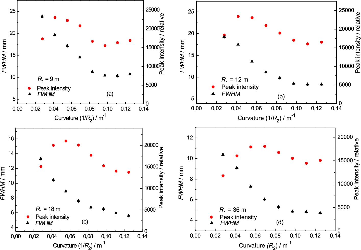
Peak intensity and FWHM of the diffraction profile dependences on the FAD crystal curvature for fixed curvatures of the Si(220) slab as registered by the scintillation camera: (a) 0.11 m−1, (b) 0.083 m−1, (c) 0.056 m−1 and (d) 0.028 m−1.
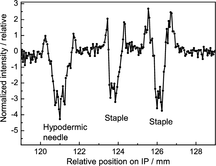
Refraction images of hypodermic needle and two office staples:
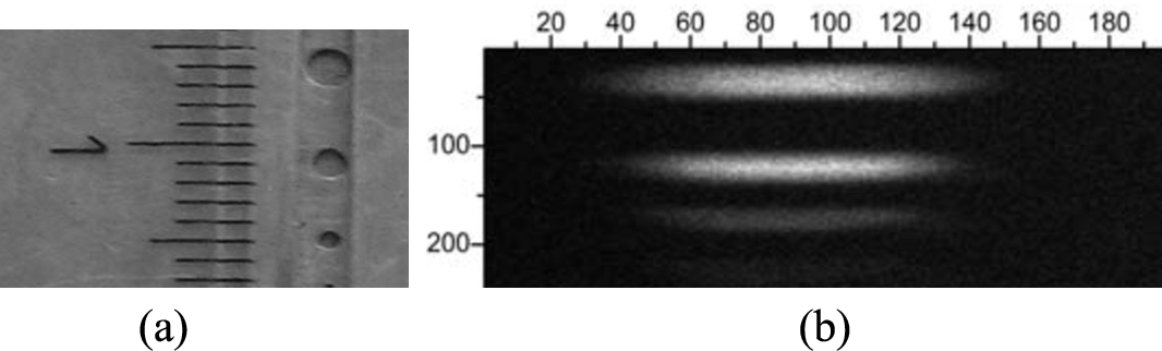
Holes in the Cd absorber vertically situated in front of the FAD crystal (a) and the image of them for
Peak intensity and FWHM of the diffraction profile dependences on the FAD crystal curvature for fixed curvatures of the Si(220) crystal as registered by the scintillation camera: (a) 0.11 m−1 and (b) 0.028 m−1.
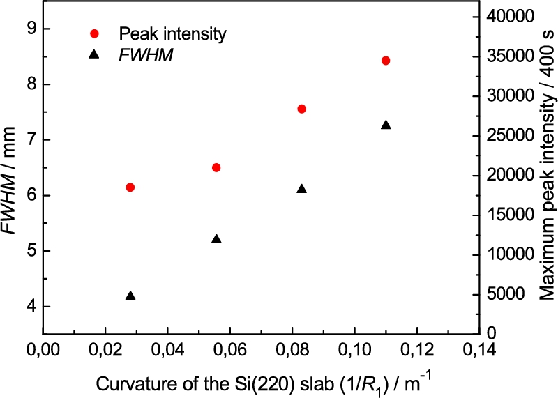
Summarized maximum peak intensity and minimum FWHM dependences on the curvature of the Si(220) slab.
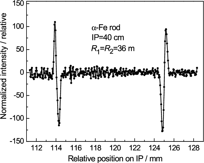
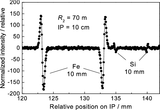
Intensity profiles related to the refraction on the edges of the 10 × 10 mm2 α-Fe rod for
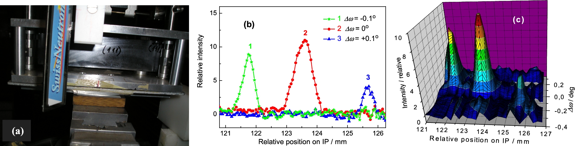
Photo of the small piece of the supermirror – (a), supermirror reflections as imaged by IP at the distance of 40 cm – (b) and 3d-representation of the reflections – (c).
By rotating the FAD-crystal slab by 180° around the vertical axis, we could test the second curvature mode, the concave curvature with respect to the detection unit. The obtained related results for two radii of curvature
The dependences of the peak intensity and FWHM of the diffraction profile on the FAD crystal curvature as registered by the scintillation camera for fixed curvatures of the Si(220) crystal: (a) 0.11 m−1, (b) 0.083 m−1, (c) 0.056 m−1 and (d) 0.028 m−1.
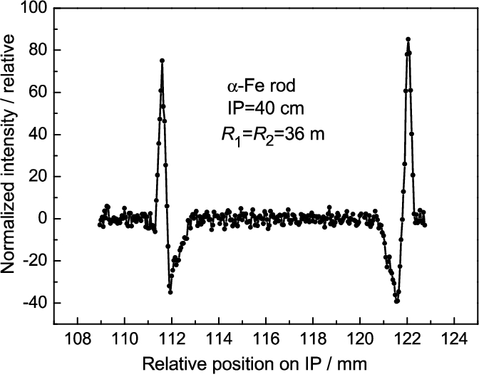
Intensity profiles related to the refraction on two edges of the 10 × 10 mm2 α-Fe rod (compare with Fig. 7).
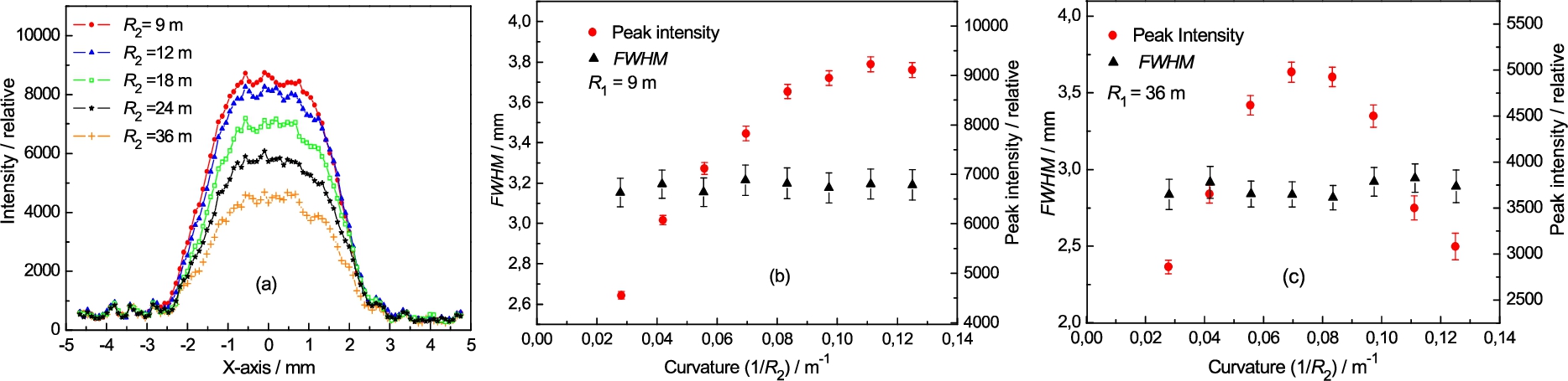
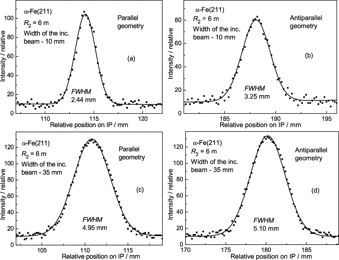
In this case, we used the opposite antiparallel diffraction geometry of the FAD crystal slab with respect to the Si(220) crystal (see Fig. 1(a), case III). Figure 9 shows the basic parameters of the output beam as a function of the curvature of the FAD-BPC slab for several curvatures of the Si(220)-BPC slab. Again, it can be seen from Fig. 9 that depending on the curvature of the FAD-BPC slab one can obtain either a wide beam, of about 20 mm, usable for some imaging experiments (see Fig. 10), or a narrow one, of about 5 mm, for some other diffraction experiments.
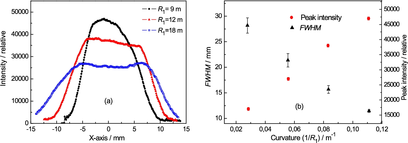
Examples of the profiles of the beam coming from the bent Si(220) crystal for radii of curvature of 9 m, 12 m and 18 m – (a) and FWHM and the peak intensity of the beam profiles related to the neighbour figure (a) measured at the place just before the FAD-BPC slab – (b).
By using this experimental performance, first, the profile of the beam coming from the Si(220) crystal and incident on the FAD crystal was measured for several curvatures. The obtained results are shown in Fig. 11. Then, as the curvature of both BPC Si(220) and Si(311) slabs were changeable, properties of the profiles of the output beam from the FAD crystal slab as registered by the scintillation camera were studied for different combinations of the crystal curvatures
Examples of the output beam diffraction profiles as registered by SC for
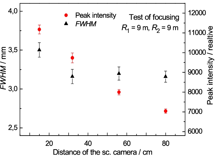
Peak intensity and FWHM of diffraction profiles taken at different distances of the camera from the FAD crystal for
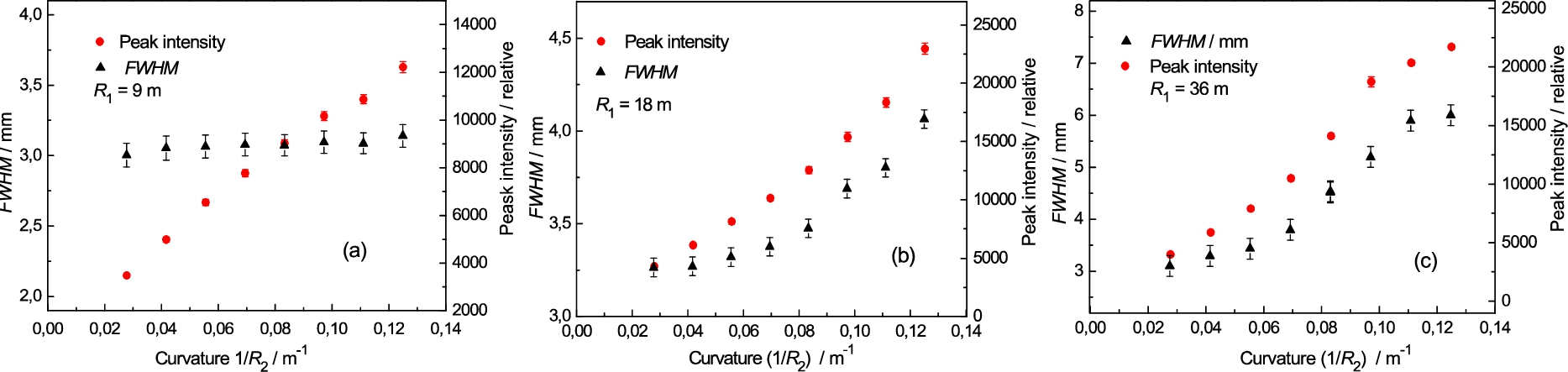
Peak intensity and FWHM of the diffraction profile dependences on the FAD crystal curvature for different radii of curvatures of the Si(220) one:
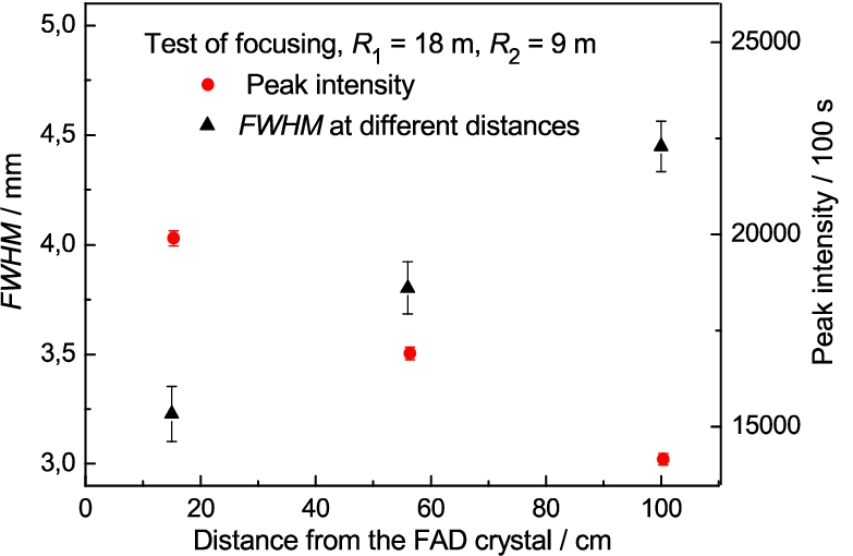
Peak intensity and FWHM of diffraction profiles taken at different distances of the camera from the FAD crystal for
In this case, the FAD-BPC slab was rotated by 180° about the vertical axis making a concave curvature with respect to the bent Si(220) slab. As the mode of the curvature of Si(220) slab and the FAD-Si(311) is the same, the double-crystal setting is less dispersive in comparison with the former case. Similarly to the case I, the properties of the beam profile as registered by the scintillation camera were studied for different combinations of the individual curvatures. The obtained results are shown in the following Fig. 14. Comparison of these figures with the related ones of the previous section reveals a big difference in the properties of both dispersive settings due to the employment of the FAD-BPC slab with the opposite mode of the curvature. As the case II is less dispersive, the peak intensity of the double-diffracted profiles is much higher and their FWHM depends on the curvatures of individual crystal slabs; for
Dispersive
DBC monochromator Si(111) + Si(311)
Finally, we tested the dispersive
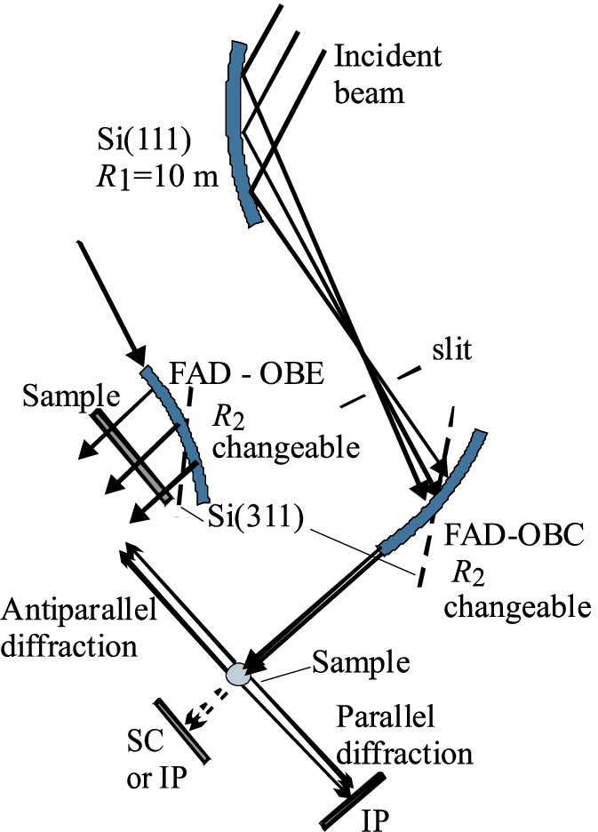
The DBC setting with the FAD-geometry of the second Si(311) crystal in OBC as well as OBE orientations.
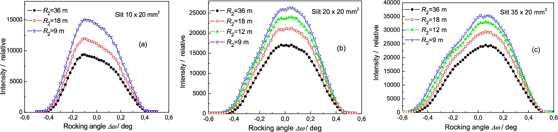
Double crystal rocking curves of the FAD crystal for three different widths of the incident beam: 10 mm – (a), 20 mm – (b), 35 mm – (c) and different radii of curvature of the second crystal slab.
First, double-crystal rocking curves were measured in order to document the effect of the width of the beam (by changing the width of the incident slit) incident on the second FAD-crystal on the luminosity of the obtained output double diffracted beam. Figure 17 shows the rocking curves obtained by rotating the second FAD crystal, in the vicinity of the Bragg condition, with respect to the first one for three widths of the incident beam. It is evident that the larger the width of the incident beam used, the higher the intensity of the double reflected beam (measured by the peak intensity of the rocking curves) can be obtained. Therefore, in the next step, the intensity of the double diffracted beam as well as FWHM of its profile for peak position on the rocking curve (
Properties of the double diffracted beam as a function of the crystal curvature imaged by the scintillation camera for different widths of the beam incident on the second crystal.
Examples of the diffraction profiles from the α-Fe(211) polycrystalline pin for two widths of the incident beam slit.
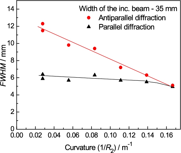
FWHMs of the beam profiles from the standard polycrystalline pin for different curvatures of the FAD slab and the incident beam slit width of 35 mm.
In this case, the FAD geometry (see insert in Fig. 16) provides a wide monochromatic beam. The incident beam is passing along the longest edge of the Si crystal and on the way, neutrons meet a large range of incident Bragg angles determined by the length of the crystal slab as well as its curvature. An example of the expansion of the monochromatic beam is demonstrated in Fig. 21 for the radius of curvature of the FAD-crystal
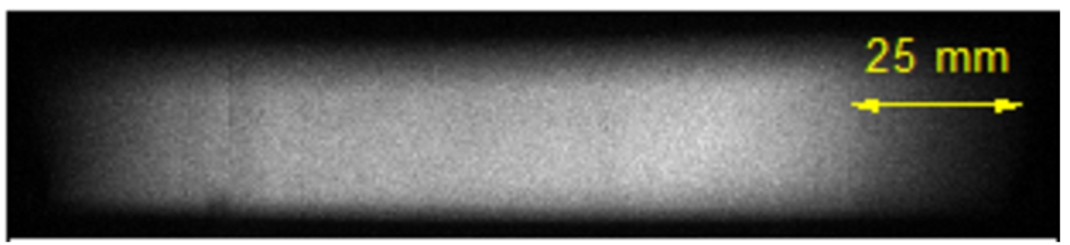
Image of the diffracted beam from the FAD-crystal in the OBE geometry for
Refraction on edges of rectangular α-Fe (1 × 1 cm2) and Si (1 × 0.5 cm2) samples.
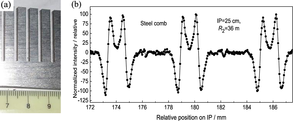
Photo of the steel comb with 4.5 × 4.5 mm2 teeth – (a) and the image of the refraction effects on the edges of the individual teeth – (b).
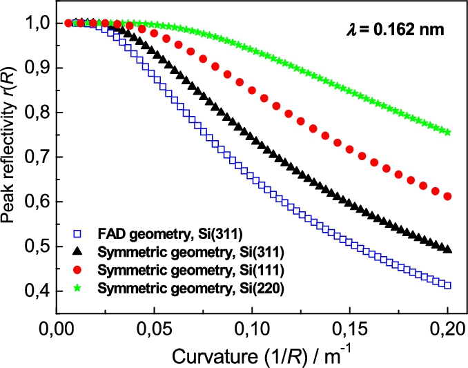
Related peak reflectivity vs crystal curvature as calculated for symmetric diffraction geometry of Si(111), Si(220) and Si(311) crystals as well as for the FAD diffraction geometry of the Si(311) one.
Some diffraction properties of the FAD geometry of the BPC Si(311) slab employed in the double-crystal settings with respect to the BPC Si(220) and Si(111) slabs were tested. Monochromatic beam provided by such a double-crystal setting is highly collimated and one can work with open beams without any Soller collimator, which is documented by several attached edge refraction images. In the case of OBC-geometry of the FAD-BPC slab, the width of the monochromatic output beam is narrow and practically determined by the thickness of the FAD crystal. Due to the mutual dispersive setting of the BPC slabs, the double diffracted beam has also a narrow
Footnotes
Acknowledgements
Measurements were carried out at the CANAM infrastructure of the NPI CAS Řež supported through MŠMT project No. LM2015056. The presented results were also supported in the frame of LM2015074 infrastructural MŠMT project “Experimental nuclear reactors LVR-15 and LR-0”. Bragg diffraction optics investigations are in the Czech Republic supported by the ESS project LM2010011: “Contribution to Partnership in Large Research Infrastructure of Pan European Importance”. We thank Ms. B. Michalcová from NPI ASCR for a significant help in the measurements and basic elaboration of the data.