This paper summarizes recent results of an exhaustive experimental study of multiple Bragg reflections accompanying allowed as well as forbidden reflections. The multiple reflection observations were carried out in the frame of Bragg diffraction optics experiments on cylindrically bent perfect single crystals. It has been found that depending on the thickness and curvature of the crystal slabs and the diffraction geometry (reflection, transmission), many strong multiple reflections can be excited which can also be used as a source of highly monochromatic and highly collimated beams for further experiments requiring extremely high resolution.
Using terminology of reciprocal lattice space, multiple Bragg reflection (MBR) effects occur when two or more reciprocal lattice points defined by the scattering vectors appear on the Ewald sphere (N-beam case, ) [2,3,26,27]. It follows from crystal symmetry that when a secondary reflection (represented by ) fulfills the Bragg condition simultaneously with the primary one (represented by ), there automatically exists a tertiary reflection defined by . As , the doubly reflected beam has the same direction as the one reflected only by the primary set of lattice planes. MBR-effects can result in the so called Aufhellung (reducing the intensity of the primary reflection) or Umweganregung (increasing the intensity of the primary reflection).
The extreme case of an Umweganregung is considered to be the effect of simulation of a forbidden primary reflection. For X-rays, positive umweg-diffraction peaks were first observed by Renninger [27], and a principal theoretical investigation in this field was first performed by Ewald [3]. Since Renninger’s first observation of MBR-peaks, many theoretical and experimental investigations of general N-beam cases, namely for the case of X-rays, have been published (see e.g. [2] and in this book many related references can be found). However, the situation in neutron diffraction is rather different. As the neutron flux is much lower in comparison to flux of X-rays, neutron diffraction is usually carried out with relaxed collimation and wavelength interval. As the reflection planes participating in the MBR-process are mutually in dispersion diffraction mode, neutron flux is usually not sufficient for the observation of such correspondingly small dynamical effects in flat perfect crystals. Therefore, in the case of neutron diffraction, MBR-effects have only been reported in a few papers. First, they were observed when accompanying allowed reflections in mosaic single crystals [1,6,25], and later [11,14,30], when simulating forbidden reflections in ultrasonically vibrating perfect single crystals. In the former case of mosaic crystals, the MBR-effects were usually smaller than 10%, while in the latter case, a few strong MBR-reflections were indicated. However, no systematic studies were carried out at that time.
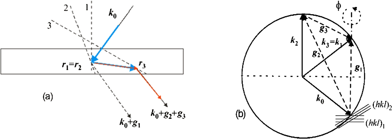
Schematic diagram of a two-step multiple Bragg reflection in real (a) and reciprocal space (b). The numbers 1, 2 and 3 represent the primary, secondary and tertiary reflection planes, respectively. is the incident wave vector and is the position where the reflection occurs.
When going back to the study of these effects after several years, recent investigations with cylindrically bent perfect crystals (BPC) [13,22,24] have shown that many strong MBR-effects could be observed simply by performing scans when setting the crystal in symmetric transmission geometry as a monochromator in the polychromatic beam and changing the Bragg angle and thus also the neutron wavelength. Attention was mainly paid to MBR-effects accompanying the forbidden reflections in elastically bent perfect crystals of Si and Ge when providing a pure highly monochromatic and highly collimated beam for possible exploitation [15,17,19,21,23]. Later for the sake of comparison, some experiments were carried out to study the problem of MBR-effects accompanying the allowed reflections [18,20]. As for the interpretation of the MBR-effects, it has been found that contrary to the dynamical diffraction on perfect crystals, the quasi-classical approach can be applied in the case of elastically deformed perfect crystals [8]. As schematically displayed in Fig. 1, based on this approach, the multiple diffraction process simulating the primary reflection at the point can be assumed as a series of successive secondary and tertiary beam reflections taking place at two different points and (which generally have different deformations), respectively. We assume that the mutual separation of these two points is larger than the extinction length. Then, on the basis of this kinematical assumption, the so-called N-beam case can be considered as a simultaneous action of several independent pairs of secondary and tertiary reflections contrary to that of perfect crystals where a dynamical neutron wave field with all momentum components is created.
The aim of this paper is to present a summary of the obtained experimental results and to show that especially in the case of elastically deformed perfect single crystals (in our case cylindrically bent perfect crystals), MBR-effects cannot be considered negligible. Moreover, as will be shown, optimally chosen multiple reflections can provide a sufficiently strong neutron signal which can be exploited for extremely high-resolution scattering studies.
Calculations
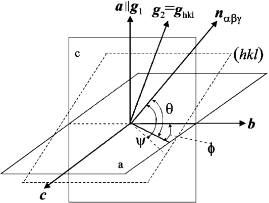
From the geometry displayed in Fig. 2, it is possible to derive the following relations [1,15]:
where is the unit vector showing the direction of the incoming neutron beam and by definition . α, β and γ are the angles between the unit vector and the vectors , and , respectively. As presented in Fig. 3, the vectors , and are in fact scattering vectors perpendicular to lattice planes parallel to the front face, the main (largest) face and the top face of the slabs, respectively (see Fig. 3). The following relation:
is deduced from the Bragg condition where d is the corresponding lattice spacing.
Coordinate system for describing the secondary reflection occurring with the basic primary reflection.
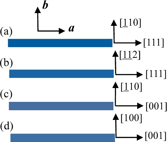
Top view on four crystal cuts of the Si and Ge slabs that were used in the experimental search of MBR effects in symmetric transmission geometry.
For each crystal slab used in our experiment, we could derive the relations providing Bragg angles θ of the primary reflection where a secondary reflection represented by the Miller indices h, k, l can lead to multiple reflections. For the crystal slab with the largest surface parallel to (110) and the longest edge parallel to [111], we have:
For the crystal slab with the largest surface parallel to (112) and the longest edge parallel to [111]:
For the crystal slab with the largest surface parallel to (110) and the longest edge parallel to [001]:
And for the crystal slab with the largest surface parallel to (100) and the longest edge parallel to [001], the Bragg angle θ is deduced from:
The parameter m in the relations (3)–(6) corresponds to the order of the primary reflection. From these relations, one can easily identify secondary and tertiary reflections participating in the MBR effect with respect to a chosen primary reflection. However, when setting the crystal in a polychromatic incident beam, the presence of higher (or lower) orders can be found. For example, if we are interested in MBR-effects with respect to the forbidden Si(222) primary reflection, in many cases we will also find MBR-contributions with respect to the primary reflections Si(111), Si(333), Si(444), etc. In practice, all undesirable higher (or lower) order contributions can be eliminated with a neutron wavelength selector or by using a pre-monochromator. The wavelength distribution of neutrons passing through a neutron guide can also suppress undesirable higher-order contributions automatically, because neutrons of shorter wavelengths are simply not reflected. We should also consider that the reflection probability related to individual secondary and tertiary reflections is rather small for shorter neutron wavelengths [7,10]. Contrary to mosaic crystals, in our case of cylindrically bent perfect crystals for detailed estimation of individual MBR-contributions, the value of the scalar product where is the displacement of atoms due to deformation also plays an important role.
In the experimental search of MBR effects, two methods are usually used:
scans with an incident white beam and a fixed azimuthal angle ϕ.
Azimuthal rotation of the crystal lattice around the scattering vector of the primary reflection.
These two methods are covered in the following sections.
Scheme of the experimental setup for the search of MBR-effects using the method of scans with an incident white beam and a fixed azimuthal angle ϕ.
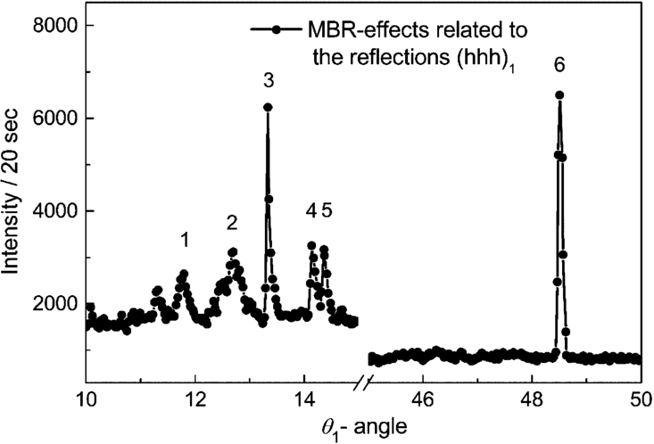
Extracts of the scan (in degrees) with a 5 mm thick slab (largest face parallel to (110)) set for the reflections in the symmetric transmission geometry and .
Extracts of the scan (in degrees) of a 3 mm thick slab (the largest face parallel to (112)) set for the reflections and .
Extracts of the scan (in degrees) of a 4 mm thick slab (the largest face parallel to (110)) set for (00l)1 reflections in the symmetric transmission geometry and .
scans with a polychromatic incident beam for a fixed azimuthal angle ϕ
Initially, in order to identify strong MBR-effects, we used three different cuts of cylindrically BPC Si-slabs (see Figs 3(a)–3(c)) deliberately in symmetric transmission geometry for using the scan method for (see Fig. 4). It is known that the integrated reflectivity of a deformed crystal is a function of the scalar product [7,8,10,29] which may be zero for the primary reflection, i.e. and whose corresponding integrated reflectivity is independent of the deformation. This is also valid in the case of cylindrical bending and symmetric transmission geometry. On the other hand, needs not be zero, and therefore the deformation can lead to a large increase of the MBR-effect while keeping the integrated reflectivity of the primary reflection constant. During the first experimental studies, many strong MBR-effects at different wavelengths were observed. Parts of the obtained scans are shown in Figs 5–7 and the corresponding calculated primary/secondary/tertiary reflections are listed in Tables 1–3. It can be seen from Fig. 5 that the strong peaks No. 1–No. 3 accompany the allowed primary Si(111) reflection. In comparison to the results obtained on mosaic crystals [1,6,25] where the contribution of the MBR-effects was rather small, the choice of a suitable diffraction geometry may result in an MBR-effect two orders of magnitude stronger than the one corresponding to the primary reflection.
The difference between the background for smaller and larger Bragg angles in Fig. 5 is brought about simply by the presence of the primary allowed Si(111) reflection.
Calculated reflections and the Bragg angles related to the strongest peaks No. 1–4 (see Fig. 5)
Peak no.
Primary / secondary / tertiary reflections
Bragg angle [deg]
1
111 / 313 / 404
11.536
1
111 / 044 / 133
11.536
1
111 / 133 / 022
11.536
1
111 / 202 / 313
11.536
2
111 / 133 / 224
13.763
2
111 / 151 / 040
13.763
2
111 / 400 / 511
13.763
2
111 / 224 / 313
13.763
3
111 / 153 / 242
14.705
3
111 / 422 / 513
14.705
4
222 / 311 / 513
29.956
4
222 / 313 / 511
29.956
4
222 / 151 / 133
29.956
4
222 / 153 / 131
29.956
Calculated reflections and the Bragg angles related to the strongest peaks No. 1–4 (see Fig. 6)
Peak no.
Primary / secondary / tertiary reflections
Bragg angle [deg]
1
111 / 533 / 642
11.653
1
111 / 353 / 462
11.653
2
111 / 426 / 535
12.804
2
111 / 246 / 355
12.804
3
111 / 311 / 400
13.262
3
111 / 131 / 040
13.262
3
111 / 331 / 440
13.262
3
111 / 220 / 331
13.262
4
111 / 242 / 351
14.173
4
111 / 422 / 531
14.173
5
111 / 335 / 444
14.420
6
222 / 111 / 331
48.527
Calculated reflections and the Bragg angles related to the strongest peaks No. 1–3 (see Fig. 7)
Peak no.
Primary / secondary / tertiary reflections
Bragg angle [deg]
1
002 / 311 / 313
23.515
1
002 / 313 / 311
23.515
1
002 / 131 / 133
23.515
1
002 / 133 / 131
23.515
2
004 / 602 / 602
27.938
2
004 / 422 / 426
27.938
2
004 / 426 / 422
27.938
2
004 / 242 / 246
27.938
2
004 / 246 / 242
27.938
2
004 / 062 / 062
27.938
3
004 / 620 / 624
29.496
3
004 / 624 / 620
29.496
3
004 / 260 / 264
29.496
3
004 / 264 / 260
29.496
Similar features are also seen in Figs 6 and 7. It should be pointed out that all MBR-effects have been identified (for more details see [13,22,24]) but, for the sake of the goals of this paper, we introduce only the description of the strongest ones. In addition, it should be pointed out that some MBR-effects related to the secondary/tertiary reflections with large Miller indexes h, k, l (one of them larger than 6) were omitted, their contribution considered to be too small. In relation to these experiments we are very grateful to GENF at GKSS for providing us with the beam time and all necessary support before the shutdown of the research reactor. It permitted us to carry out the presented scans on the diffractometer POLDI installed at the thermal neutron guide. This allowed us to avoid all possible MBR-contributions corresponding to neutron wavelengths smaller than 0.08 nm (higher orders).
Some MBR-effects studied by the TOF method
As far as we know, practically all neutron diffraction studies of MBR-effects have been carried out at steady state neutron sources. Here, we present the data collected in TOF mode at a Linac accelerator based small neutron source. For this investigation of MBR-effects by the TOF method, three Si slabs of different cuts were used (see Fig. 3). During the experiment, all crystal slabs were set in the symmetric transmission diffraction geometry as schematically displayed in Fig. 4, but at chosen (fixed) angles. Several rather strong MBR-effects already known from earlier diffraction measurements carried out by the scanning method with a white beam at fixed azimuthal angle were chosen for the TOF studies.
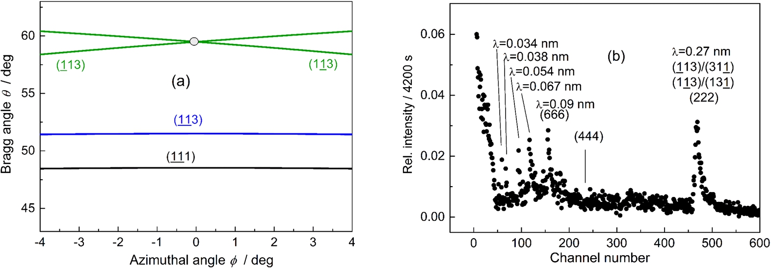
(a) – Part of the ϕ vs θ relationships for the Si(222) primary reflections for the slab having the main face parallel to (110) planes and (b) – the related TOF spectrum taken with the 3.7 mm thick bent Si slab () set for the forbidden reflection at .
The TOF experimental investigations were carried out at the cold neutron source of the Hokkaido University in Sapporo [9] by using a flight path of about 7 m. Figures 8–10 show a few of the obtained TOF spectra for the Si(222) and Si(002) primary reflections. The chosen experimental points are marked by circular points. As no reflection for longer λ were observed, and for a better visibility of the effects visible at shorter λ, only the first part of the spectra up to the channel number 600 (instead of 1024) is plotted. At the shorter λ, the density of reciprocal points in the reciprocal space is important. Consequently, the number of pairs of secondary/tertiary reflections increases and only neutron wavelengths () are marked.
(a) – Part of the ϕ vs θ relationships for the Si(222) primary reflections for the slab having the main face parallel to (110) planes and (b) – the related TOF spectrum taken with the 3.7 mm thick bent slab () set for the forbidden reflection at .
(a) – Part of the ϕ vs θ relationships for the Si(002) primary reflections for the slab having the main face parallel to the main face parallel to (110) planes, (b) – the related TOF spectrum taken with the 4.1 mm thick bent slab () set for the forbidden reflection at .
It is clear from Figs 8–10, that the MBR-effects in elastically bent perfect crystals can be investigated even at small accelerator-based neutron sources. Interestingly, there are no diffraction peaks of some allowed reflections e.g. Si(111), Si(333) or Si(555). In the case of Fig. 10, small peaks connected with the MBR-effect are observed at the positions of the 004 and 008 reflections of the TOF-spectrum.
Due to a weak diffraction signal, allowed primary reflections realized only through symmetric transmission are not visible above the background, or remain very small. This corresponds to the fact that for the primary reflections as well as are valid and from the point of reflectivity the bent crystals behave as perfect nondeformed crystals. On the other hand, the MBR-effects could be considerably strengthened by elastic deformation.
Schematic setting used for MBR studies at the dedicated diffractometer by the ϕ and θ scanning.
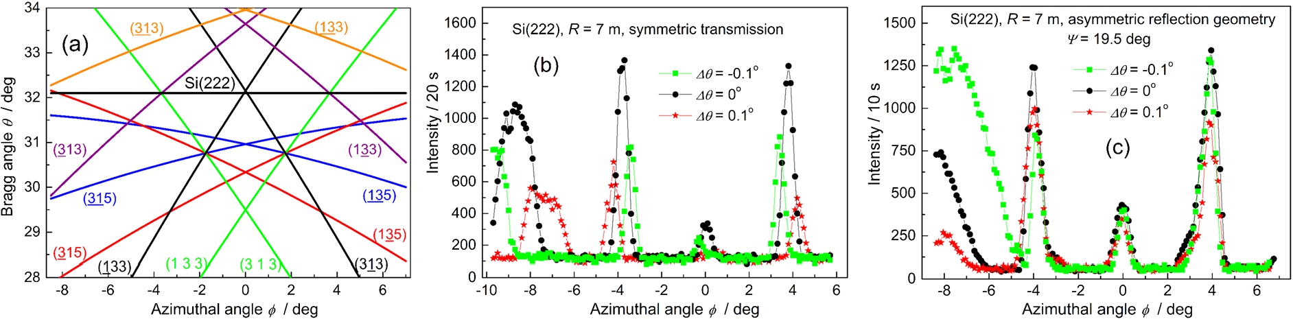
(a) – Part of the ϕ vs θ relationship for Si(222) primary reflection of the diamond structure for the main face of the slab parallel to the planes (112), (b) – experimental scans for symmetric and (c) – asymmetric diffraction geometries of Si slabs for different deviations from the mean Bragg angle at . Ψ is the degree of asymmetry with respect to the main face; .
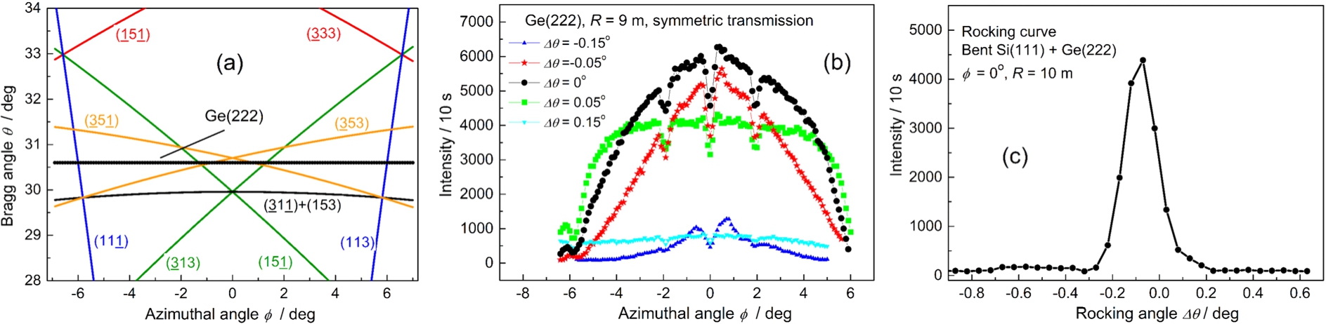
(a) – Part of the ϕ vs θ relationship for Ge(222) primary reflection of the diamond structure for the main face of the slab parallel to the planes (110), (b) – experimental scans for Ge slab and different deviation from the mean Bragg angle at , (c) – rocking curve of the Ge(222) with respect to the bent Si(111) pre-monochromator; .
MBR-effects accompanying forbidden reflections studied by azimuthal rotation of the primary crystal lattice around its scattering vector for a fixed neutron wavelength
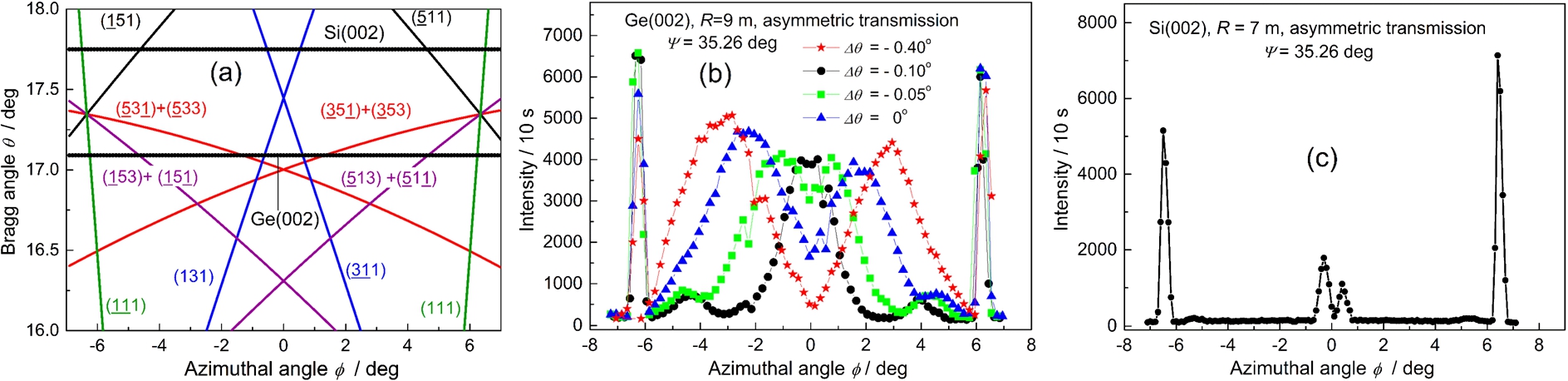
As all our diffractometers in Řež operate at constant neutron wavelengths, we used the method of the azimuthal rotation of the crystal lattice around the scattering vector of the primary reflection (see Fig. 11) for searching and studying the MBR-effects. In order to avoid MBR-effects accompanying higher- and lower-order primary reflections, in most experiments we used the double-axis diffractometer having a bent Si(111) pre-monochromator with a fixed bending radius . The first experiments were carried out at a wavelength . The next ones were performed after a new installation of the monochromator at a slightly changed wavelength of 0.162 nm. The bent crystal slab used for the experimental MBR studies was situated on the second axis. The dimensions of the slabs (see Fig. 3) were 200 × 30 × (3–5) mm (length × width × thickness). In some cases, asymmetric diffraction geometries were possible. Figure 12 shows the ϕ vs θ relationship for the MBR occurrences related to the forbidden Si(222) reflection and the corresponding experimental scans. The horizontal straight line corresponds to the line of the ϕ-rotation at a constant mean Bragg angle of the primary reflection. corresponds to the position of the crystal slab with the (112) planes perpendicular to the scattering plane. At the fixed wavelength of 0.166 nm, the azimuthal scan was carried out at the Bragg angle when following the horizontal line in Fig. 12(a). The incident beam section was about 1 cm2. It can be seen from Fig. 12 that the intensity of the MBR-effects strongly depends on the diffraction geometry. This is because the reflectivity of the individual diffraction processes depends on the value of the scalar product [7,8,10,29]. Figure 13 shows a similar ϕ vs θ relationship and experimental scans but for a Ge crystal slab having the main face parallel to the (110) planes. It should be pointed out that, from a formal point of view, the combination bent Si(111) + Ge(222) is strongly dispersive and the MBR beam is highly collimated. Therefore, the width of the rocking curve (see Fig. 13(c)) is determined only by the divergence of the incident beam from the bent Si(111) monochromator. The next Fig. 14 demonstrates several experimental results related to the forbidden (002) reflection of Si and Ge slabs. In this case we used the crystals with the main face parallel to the (112) planes (see Fig. 3(b)) which also provided the possibility of an experimental search for MBR-effects related to the (002) reflection in asymmetric diffraction geometry when the (002) lattice planes are at an angle of with respect to the main face of the slab. It can be seen from Figs 12–14 that in all cases strong MBR-effects were observed. Furthermore, the inspection of the scans reveals that the observed MBR-effects are realized at azimuthal angles ϕ where a constant θ-line intersects the occurrence lines. However, MBR-effects are not observed at all intersections because the related intensity depends on several parameters: the bending radius, the reflectivity of the individual lattice planes participating in the MBR process and the orientation of their scattering vectors , with respect to the vector displacement representing the crystal deformation.
(a) – Part of the ϕ vs θ relationship for 002 primary reflection of the diamond structure, (b) – experimental scans for Ge and Si slabs and different deviations from the mean Bragg angle; .
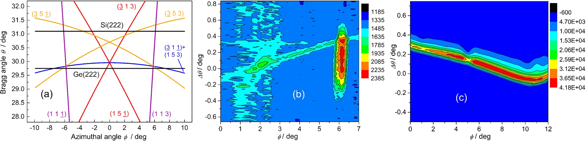
(a) – Part of the ϕ vs θ relationship for 222 primary reflections of Si and Ge crystals at the vicinity of the Bragg angle of 30° for the main face of the slab parallel to the planes (110), (b) – two dimensional distribution of the intensity vs the azimuthal angle ϕ and for Si(222) and (c) – Ge(222); .
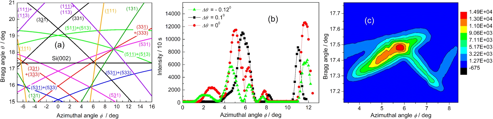
(a) – Part of the ϕ vs θ relationship for Si(002) primary reflection at the vicinity of the Bragg angle of 17.5° for the main face of the slab parallel to the planes (110), (b) – the intensity vs ϕ scans for different deviations from the mean Bragg angle and (c) – the detail of the two dimensional map of the intensity vs ϕ in the vicinity of and the mean Bragg angle θ; .
After a new installation of the monochromator, several experiments were repeated with a slightly changed wavelength of 0.162 nm which of course had a substantial effect on the occurrence of the MBR-effects because of a shift of the horizontal θ-line and a change of intersection points. Figure 15 displays the area of the ϕ vs θ map of the MBR occurrences with two dimensional experimental scans taken with Ge(222) and Si(222) slabs. The section of the incident beam coming from the bent Si(111) pre-monochromator was 20 × 10 mm2 (height × width). Strong MBR-effects were observed in both cases, though mutually differing by the mean Bragg angle. The inspection of Fig. 15(b) reveals that the strongest maximum is obtained when the (113) and (111) planes cooperate. On the other hand the weaker MBR-effect observed in the vicinity of corresponds to the cooperation of the (353)/(531) together with (313)/(511) planes. However, by using the Ge crystal slab instead of the Si one, a much stronger MBR-effect was observed, though the thickness of the bent Ge crystal was only 2 mm. The inspection of Fig. 15(c) reveals that the most important role with respect to the MBR effect is due to the cooperation of two pairs of secondary and tertiary reflection planes, namely (311)/(513) and (153)/(131). However, in the vicinity of the additional Aufhellung effect can be seen and comes from the competing presence of (113)/(111) and (351)/(533). Similarly, Fig. 16 shows a few experimental results obtained with a Si(002) slab when using a section of the incident beam of 20 × 20 mm2. The inspection of Fig. 16(b) reveals that the MBR effect for and comes from the cooperation of the (331)/(333) + (333)/(331) planes. The neighbouring MBR-effect at is brought about by the cooperation of (111)/(111) planes. After setting the crystal to the position of , two MBR-effects seen at and for join in a single maximum at .
A detail of the two dimensional map of the observable MBR-effects obtained on the basis of a series of rocking curves of the bent crystal slab with respect to the Si(111) pre-monochromator in the vicinity of the mean Bragg angle and is shown in Fig. 16(c). The MBR-effect observed in the vicinity of comes from the cooperation of two pairs of secondary/tertiary lattice planes, i.e. (111)/(113) + (113)/(111). If we compare the strongest MBR effects related to the Ge(222), Si(222) and Si(002) forbidden reflections, the setup with the Ge slab provides a much higher monochromatic beam flux (about 4000 neutrons per second for and ), which can be exploited for practical use and will be documented later.
(a) – Part of the ϕ vs θ relationship for Si(002) primary reflection of the diamond structure and (b) – scans for the forbidden reflection and three values of in the vicinity of the Bragg angle ; .
(a) – Part of the ϕ vs θ relationship for Si(222) primary reflection in the vicinity of the Bragg angle 44.41° for the main face parallel to the planes (110) and (b) – the intensity vs ϕ scans for and at .
By using another diffractometer, for the sake of comparison, we also measured several ϕ vs θ scans taken at larger neutron wavelengths when the density of MBR occurrences is much smaller than it was for the shorter wavelengths. First, the crystal slab having the main face parallel to the (100) planes was set for the forbidden Si(002) reflection at the mean Bragg angle () in symmetric transmission geometry. Figure 17(a) displays the part of the ϕ vs θ map of MBR occurrences in the vicinity of the mean Bragg angle for the Si(002) slab. In this case the scans follow the Eq. (6). It can be seen from Fig. 17(b) that the strongest MBR-effect for positive values of ϕ is generated by the cooperation of two pairs: the (311)/(313) and (313)/(311) planes.
A similar measurement was then carried out with the crystal slab (see Fig. 3(a)) having the main face parallel to the (110) planes and set for the forbidden Si(222) primary reflection in symmetric transmission geometry at the mean Bragg angle . Several related results are shown in Fig. 18 for the radius . The inspection of Fig. 18(b) reveals strong MBR-effects for , and where four pairs of secondary/tertiary reflections participate in the MBR process. It is clearly visible for when the shift of the Bragg angle results in a splitting of the single peak into four.
(a) – Part of the ϕ vs θ relationship for 111 primary reflection of the diamond structure, (b) – the two-dimensional distribution of the intensity of the MBR-effects versus the azimuthal angle, and (c) – the profiles of the beam diffracted by the crystal as taken by SC for two positions. The cross-section of the beam coming from the monochromator was 20 × 20 mm2.
MBR-effects accompanying the allowed reflections
Si(111) case
Contrary to our earlier investigations of MBR-effects related to forbidden primary reflections Si(222), Ge(222) or Si(002), Ge(002) [18,20], we focus here on the investigations of the MBR-effects related to the strong Si(111) primary reflection. We used the method of azimuthal rotation around its scattering vector (ϕ-scan) at a fixed neutron wavelength . The 3.7 mm thick crystal slab was cut with the main face parallel to the planes (110). Symmetric transmission geometry was deliberately chosen in order to keep the scalar product .
Figure 19(a) shows the part of the ϕ vs θ relationship for Si(111) primary reflection in the vicinity of the mean Bragg angle of 15° for which the diffractometer was adjusted. Figure 19(b) presents experimental results containing the MBR-effect observed for different values of the azimuthal angle ϕ, and with respect to the strongest MBR-effect observed in the vicinity of . In the case of the absence of the MBR-effect, the intensity profile corresponding to the allowed reflection should be constant. Figure 19(c) shows the profiles of the beam diffracted by the second MBR crystal for and two -positions as taken by the scintillation camera (SC) where one can easily distinguish the contribution of the allowed reflection (a wide flat base) from the MBR-effects appearing as Gaussian peaks. The peak in the profile for corresponds to the contribution of the (260)/(351) planes and the peak in the profile for corresponds to the contribution of the (422)/(513) planes.
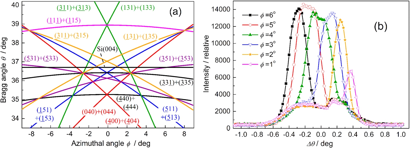
(a) – Part of the ϕ vs θ relationship for the 004 primary reflection of the diamond structure and (b) – several chosen rocking curves of the Si(004) slab taken in the vicinity of the mean Bragg angle .
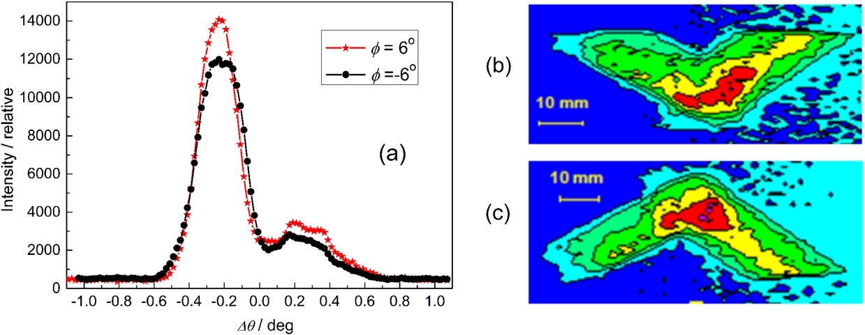
Example of rocking curves for two opposite values of ϕ – (a) and two related images of the MBR beam collected by the IP: , – (b) and , – (c).
Si(004) case
Similarly to the previous case, we carried out specific studies of the MBR-effects accompanying a strong Si(004) reflection in the bent perfect crystal (cut shown in Fig. 3(c)) at . Figure 20(a) shows the related ϕ vs θ relationship where the horizontal straight line corresponds to the Si(004) reflection for . For this experiment, the beam incident to the slab was limited to a section of 5 × 10 mm2 (width × height). Due to the construction of the bending device, the azimuthal angles ϕ could only range from −8° to 6°. Figure 20(b) shows several rocking curves of the bent Si(004) slab () with respect to the Si(111) monochromator. The inspection of Fig. 20(a) reveals that the MBR-effects are mainly generated by the cooperative action of the secondary/tertiary reflections (351)/(353) + (353)/(351) for the positive values of the azimuthal angles, and (531)/(533) + (533)/(531) for negative ones, for different ϕ with a different power. It should be noted that in this case the conditions of appearance of the MBR-effects are the same for the negative values of the azimuthal angle ϕ (see Fig. 20(a)). It can be seen from Fig. 20(b) that the peaks corresponding to the MBR-effects are situated on a fairly wide angle which corresponds to the allowed Si(004) reflection. Its width is given by a strong dispersive double-crystal setup Si(111) + Si(004). Figure 21 shows examples of the rocking curves for two opposite values of ϕ and related images of the output MBR beam. Slight differences between the rocking curves in Fig. 21(a) are given by a small difference in the absolute value of the azimuthal angle because the experimental position of is influenced by the error in cutting the crystal slab with the main face parallel to the lattice planes (110). The creation of the wings points out a very important characteristic of the MBR-effects in the case of bent perfect crystals, i.e. that the individual components of the pairs of secondary/tertiary reflections e.g. (351)/(353) + (353)/(351) or (531)/(533) + (533)/(531) can be isolated (e.g. with slits) which is not possible in the case of nondeformed perfect or mosaic crystals. In addition, with a suitable choice of the azimuthal angle ϕ and the rocking angle , the signal corresponding to the MBR effect can almost be separated from the primary allowed reflection (see Fig. 20(b)).
Powder and single crystal diffraction tests
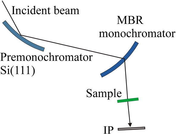
The first attempts to use the MBR monochromator were performed just after the first observations of strong MBR-effects at the low power reactor in GKSS Geesthacht on the diffractometer Poldi installed at the thermal neutron guide (see Figs 5–7). Figure 22 shows the simple experimental configuration used in the powder and single crystal diffraction tests [13].
Schematic arrangement used for powder and single crystal diffraction tests with the MBR monochromator.
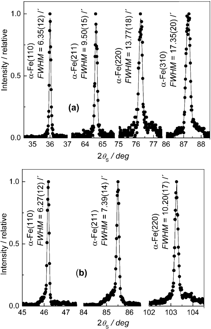
Examples of α-Fe diffraction lines taken with the MBR-monochromator and a solid poly-crystalline sample at (a) – and (b) – in configuration. FWHM is in minutes of arc.
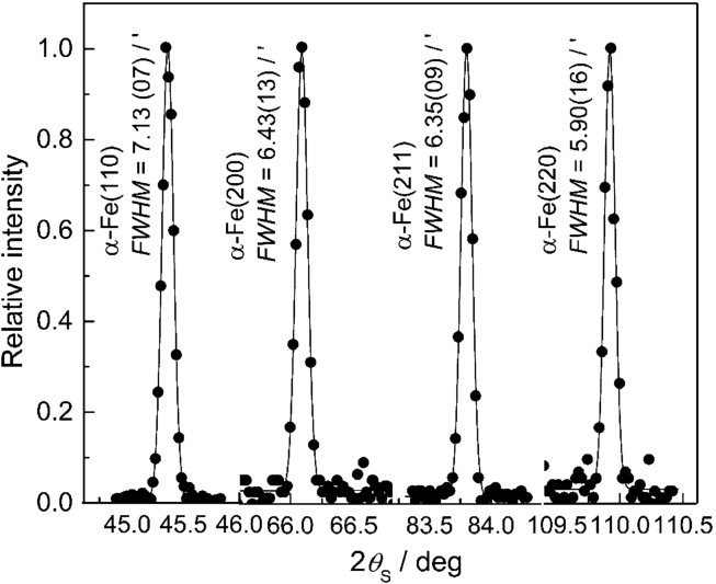
Examples of the profiles taken from the 2 mm α-Fe pin with using the Si(222) MBR-monochromator for nm and .
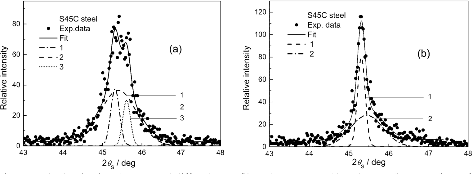
Induction-hardened S45C steel diffraction profiles taken at 2 mm (a) and 4 mm (b) under the surface with the fitted profiles related to (a) – the ferrite (1) and martensite (2) phases and pearlite structure (3) and (b) – ferrite (1) and martensite (2) phases, respectively. The configuration was used.
Figure 23 displays several diffraction profiles of a standard α-Fe polycrystalline sample taken with a MBR-monochromator set at two neutron wavelengths related to the peaks No. 1 () and No. 3 () in Fig. 5. Even though the MBR-effects accompany the allowed reflection Si(111), they clearly prove their applicability for high-resolution diffraction studies when the contribution of the allowed primary reflection can be considered as background. In this case, the FWHM of the diffraction profiles are mostly determined by the spatial resolution of the position sensitive detector PSD (1.5 mm) and the widths of the input and output slits situated before and after the sample, here respectively 5 and 2 mm. Later, a similar powder diffraction test (Fig. 24) was carried out for where a strong MBR-effect is observed due to the simulation of the forbidden Si(222) reflection by cooperative action of 153/131 + 313/511 + 151/133 + 311/513 (secondary/tertiary) reflections at [22]. As the secondary and tertiary lattice planes are mutually in dispersive mode, the outgoing monochromatic beam from the MBR-monochromator is highly parallel with a divergence of about and an excellent resolution [6]. In this case, a solid α-Fe polycrystalline pin with the diameter of 2 mm was used. Contrary to the conventional powder diffractometer, it can be seen from Fig. 24 that thanks to the excellent properties of the beam coming from the MBR-monochromator, a small FWHM is kept at large scattering angles. However, the FWHM of the diffraction profiles remain influenced by the spatial resolution of the used PSD (1.5 mm) and the 2 mm width of the sample. Therefore, the measured FWHM can be considered as an upper limit.
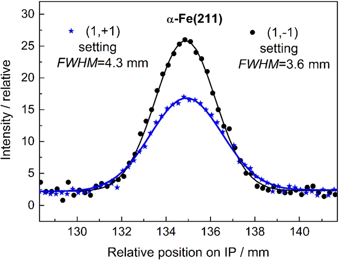
Diffraction profiles taken from the polycrystalline α-Fe(211) plate of the width of 7 mm and the thickness of 2.5 mm.
Then, we exploited this resolution for identification of Fe structures with close lattice constants and contained in an induction hardened S45C steel rod of 20 mm diameter. The sample had a different phase/structure composition at different distances from its axis. The gauge volume was fixed with 2 mm wide slits in the incident as well as the diffracted beam. Figure 25 displays the diffraction profiles obtained at a distance of 8 and 6 mm from the rod axis. Thanks to the high-resolution monochromatic beam, after a fitting procedure on the experimental data and followed up Gaussian deconvolution, we could identify the presence of the individual structures even at the low-power reactor in GKSS Geesthacht.
Further powder diffraction tests were carried out with the MBR-Ge(222) monochromator (see Fig. 13) with the α-Fe(211) sample in the form of a 2.5 mm thick plate with 7 mm width. The sample was put on the diffractometer with the main face perpendicular to the open incident beam (without input slit). As the scattering angle was 90.2°, the beam diffracted by the sample was practically parallel to the main face of the sample and no output slit was used. Then, two image plates at a distance of 40 cm from the sample were placed on the left side (parallel configuration) as well as on the right side (antiparallel configuration) with respect to the incident beam. The obtained diffraction profiles shown in Fig. 26 confirm the high-resolution characteristic of the MBR beam also in the antiparallel setting.
As the secondary and tertiary planes are mutually in the dispersive diffraction mode, one can also expect an excellent monochromaticity of the 10 mm MBR-beam which is documented by the rocking curve of a slightly bent Si(422) with respect to Ge(222) deliberately done in configuration (see Fig. 27).
Rocking curve of a slightly bent Si(422) with respect to Ge(222) crystal mutually in the antiparallel configuration.
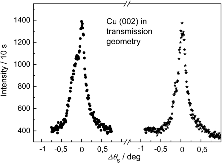
Rocking curves of the Cu(002) mosaic monochromator taken in the antiparallel configuration with respect to the Ge(222) crystal.
One of the possible uses of an MBR beam is for testing the mosaic distribution of real crystals e.g. mosaic monochromators. Figure 28 shows an example of two rocking curves measured from a 10 mm thick Cu(002) monochromator with a 5 mm wide MBR beam for two positions separated by 10 mm. In order to demonstrate the high-resolution properties of the MBR beam, in both cases of the rocking curves, the antiparallel diffraction configuration was chosen.
Radiography tests
Conventional radiography
Scheme of the configuration employed for the radiography tests [17].
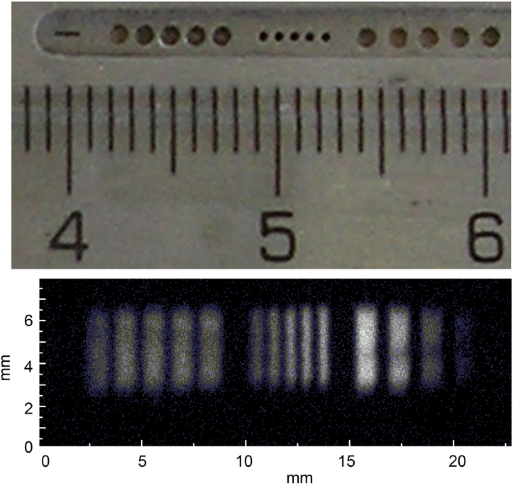
On the basis of the results shown in Fig. 13(b) and Fig. 13(c), after setting a sample (holes in Cd absorber) just behind the bent Si(002) slab (), some properties of the beam obtained by the strong MBR-effect for and could be observed (for configuration see Fig. 29). First, it should be mentioned that for the 2 × 2 cm2 incident beam the MBR effect at provides a wide highly parallel monochromatic beam of about 2 cm. Figure 30 shows the image of the holes as taken by the image plate (IP) at a rather large distance of 60 cm. The inspection of this figure reveals that the individual images are inclined with respect to the scattering plane, but they are very well separated due to the very high collimation of the MBR beam in one direction. However, in the perpendicular direction, there is a strong influence of the vertical divergence of the beam coming the Si(111) pre-monochromator. It means that the MBR-beam is highly collimated in the tangential direction with respect to the line represented by the (331) + (333) secondary reflections but not in the perpendicular direction (see Fig. 16(a)).
(Top) – photo of the holes in Cd sheet. (Bottom) – corresponding image taken by IP at a distance of 60 cm from the sample.
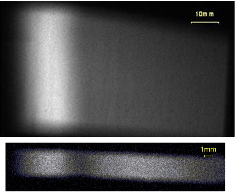
(Top) – image of the MBR beam obtained by the bent Ge(222) for an incident beam section of 20 × 40 mm2 (width × height). (Bottom) – image for an incident beam section of 5 × 4 mm2.
In order to use the highest neutron flux produced by the MBR-effect, the azimuthal angle of the Ge(222) slab (see Fig. 15(c)) was set at . Figure 31 displays two images of the MBR beam taken with the IP just behind the Ge(222) slab for two different incident beam sizes: 20 × 40 mm2 and 5 × 4 mm2.
(Top) – photo of the holes made in Cd sheet. (Bottom) – corresponding image taken by IP at a distance of 65 cm for 18 mm wide incident beam.
(Top) – photo of the slits of different widths performed in the Gd sheet. (Bottom) – corresponding intensity profiles.
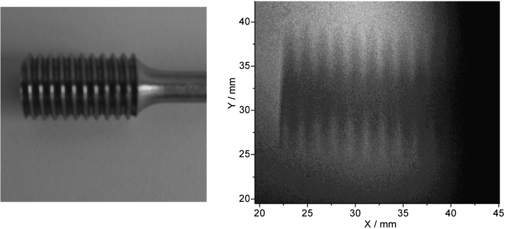
Photo of the steel screw (left) and its radiography image (right).
It can be seen from Fig. 31 that depending on the width of the beam coming from the bent Si(111) crystal, both the nonhomogeneous monochromatic beam distributions and the total widths of the MBR-beam differ. This results from the differently realized MBR-effects of the (311)/(513) and (153)/(131) pairs inside the Ge crystal. The beam image at the bottom of Fig. 31 also shows that for a rather narrow incident beam (5 mm) the MBR contributions from the individual pairs are spatially separated when realized in the opposite direction inside the bent Ge crystal with respect to the place of the incident beam [16]. This is a unique property of the elastically deformed crystal because such separation cannot be realized in a perfect or mosaic single crystal. Again, by setting the same sample as in the case of Fig. 30 (holes in the Cd absorber) just after the Ge(222) crystal, the image taken at a distance of 65 cm confirms the excellent horizontal collimation of the MBR beam which is less than (see Fig. 32). It should be noted that when using IP for imaging experiments, no special measures were made to reduce the neutron background by a shielding of IP. However, the electronic background was reduced to a minimum. The excellent collimation of the MBR beam in the horizontal plane was also confirmed by imaging the slits (performed in the Gd absorber) at a distance of 70 cm (see Fig. 33). Different heights of the peaks in Fig. 33 result from a nonhomogeneous spatial distribution of the MBR beam and therefore, this phenomenon has no special physical meaning.
A further testing was carried out at a neutron wavelength of [12]. In this case the monochromator used the MBR-effect realized on one pair of secondary/tertiary reflections (111)/(331). Figure 34 shows the image of a steel screw used in a tension/compression rig taken with the IP at a distance of 70 cm from the sample. The inspection of Fig. 34 reveals that the obtained image clearly proves the excellent horizontal resolution of the highly parallel beam in the horizontal plane. However, the influence of the vertical beam divergence remains rather large.
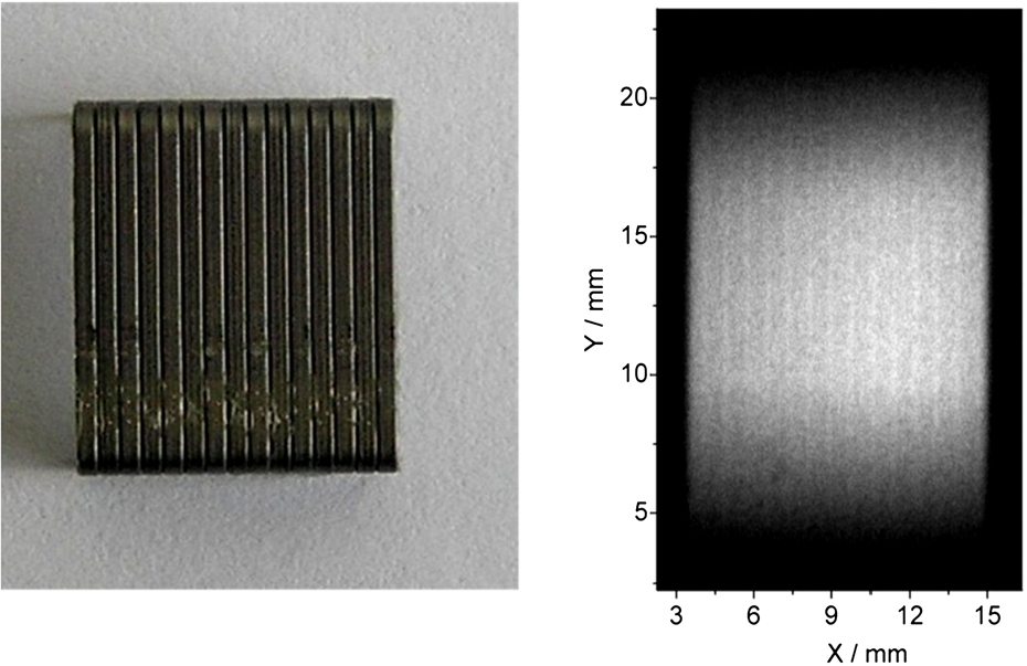
(Left) – photo of the office staples 24/6. (Right) – corresponding radiography image taken with IP at a distance of 70 cm from the sample.
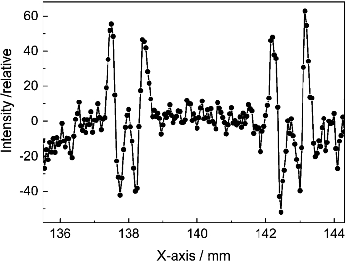
Image of two individual office staples situated in the MBR beam of the smaller width (see Fig. 31, part on the bottom).
Edge refraction experiments
This edge refraction experiment was motivated by radiography test [12] with a longer neutron wavelength of on office staples (see Fig. 35). The image was taken at a distance of 70 cm. The thickness of the office staples was only a few tenths of a millimeter and we assumed that the contrast seen on the obtained image was not based on the absorption, but thanks to high beam monochromaticity and collimation on the refraction principle occurring at the edges between the individual staples. This assumption was confirmed by the next experiment on two office staples of the same type and documented in Fig. 36. The MBR beam was obtained by a bent Ge(222) (see Fig. 15(c)) and with a narrower 5 × 4 mm2 incident beam from the monochromator for the neutron wavelength and [17]. The inspection of Fig. 36 reveals that the high quality of the MBR beam permits the investigation of refraction effects at sharp edges [4,5] even on a conventional diffractometer.
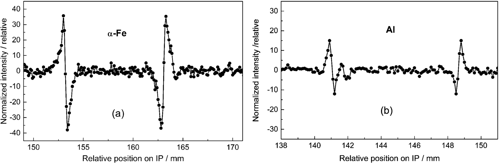
Experimental edge profiles obtained on both sides of the squared 9 mm α-Fe (a) and the squared 8 mm Al (b) prisms as registered by IP at a distance of 45 cm from the sample.
Similarly, the edge refraction effects were observed with a beam obtained by the MBR beam realized on the pair of lattice planes (351)/(353) + (353)/(351) () and accompanying the allowed Si(004) reflection (see Figs 20–21). As an example, Fig. 37 shows the edge effects imaged on two sides of a squared 9 mm α-Fe and 8 mm thick Al prism for a bending radius of the Si slab of 12 m. It can be seen that the edge effect is significantly smaller for the Al sample than the α-Fe one.
Conclusion
The presented experimental results document that in the course of experiments with elastically deformed single crystals (in our case cylindrically Si and Ge bent perfect crystals), we can predict the possible appearance of non-negligible MBR-effects and their influence on the data analyses of neutron scattering studies.
As to the interpretation of the MBR-effects, contrary to the dynamical diffraction on perfect crystals or the kinematical diffraction on mosaic crystals, the quasi-classical approach can be used in the case of the elastically deformed perfect crystals. The multiple diffraction process simulating the primary reflection can be assumed to be a series of successive secondary and tertiary reflections taking place at two different and mutually separated places of the bent crystal. In comparison to the case of mosaic crystals, in special diffraction geometry of bent perfect crystals, the MBR-effects cannot only simulate a forbidden reflection, but also substantially increase the intensity of accompanying rather strong allowed primary reflections. The strength of the MBR effects depends on the mutual orientation of the scattering vectors with respect to the displacement of atoms due to deformation, the thickness and radius of curvature of the crystal slab R and the neutron wavelength λ.
The easiest way to observe MBR effects is to use a diffraction configuration where for the primary reflection and its higher orders is valid. In most cases of our investigations, this was fulfilled by using symmetric transmission geometry of the bent crystal slab. Depending on the bending radius of the crystal slab, the resolution and the collimation (in rad) can be continuously adjusted in the range of – without any collimator. It has been shown that MBR reflections realized in bent perfect crystals can in some cases provide intensive highly monochromatic and highly collimated beams of a rather large cross-section permitting their use in special neutron experiments requiring very high resolution. Due to the dispersive mode of the secondary and tertiary reflections, the diffractometers equipped with MBR-monochromators can also provide very high resolution at low take-off angles, which can be comparable to that of back-scattering instruments.
Feasibility of their use as high-resolution monochromators has been experimentally demonstrated on several examples obtained at rather low-flux neutron sources. It is clear that the multiple reflections can also be used for the high-resolution analysis of the scattered beam, as well as for the high precision λ-calibration of e.g. TOF neutron scattering devices. MBR beams may offer an opportunity for development of high-resolution radiography which requires a rather large distance between the sample and the imaging device. Of course, they could be more efficiently exploited at high-flux neutron sources. For possible practical use of the MBR effects, optimum parameters with respect to the performance of the scattering device should be found (choice of a strong multiple reflection, crystal cut, thickness and bending radius). As there are still opened questions which need to be solved, carrying out Monte Carlo simulations would be desirable [28]. This would be very useful in cases where the MBR monochromator would be envisaged for practical exploitation.
Footnotes
Acknowledgements
Measurements were carried out at the CANAM infrastructure of the NPI CAS Řež. The presented results were also supported by the infrastructural MŠMT project LM2018120 (Experimental nuclear reactors LVR-15 and LR-0). P. Mikula acknowledges support from the ESS participation of the Czech Republic – OP (CZ.02.1.01/0.0/0.0/16_013/0001794) and J. Šaroun acknowledges support from the project ESS Scandinavia-CZ II (LM2018111). Furthermore, V. Ryukhtin and P. Strunz acknowledge support from the Czech Academy of Sciences in the frame of the program “Strategie AV21, No. 23”. For the work summarized here, we thank Drs. P. Lukáš, M. Vrána†, J. Kulda, V. Davydov, V. Wagner, M. Furusaka and V. Em for their valuable cooperation and contribution to some specific experiments and B. Michalcová for significant help with measurements and basic elaboration of the data.
References
1.
K.Blinowski and J.Sosnowski, Parasitic reflections of neutrons in crystal monochromators, Nucl. Instrum. Methods10 (1961), 289–294. doi:10.1016/S0029-554X(61)80121-3.
2.
S.-L.Chang, X-Ray Multiple-Wave Diffraction: Theory and Application, Springer Series in Solid-State Sciences, Vol. 143, Springer-Verlag, Berlin–Heidelberg–New York–Tokyo, 2004.
3.
P.P.Ewald, Zeitschrift für Kristallographie A97 (1937), 1–27.
4.
N.Kardjilov, Further developments and applications of radiography and tomography with thermal and cold neutrons, PhD thesis Technische Universität München, Germany, 2003.
5.
N.Kardjilov, S.V.Lee, E.Lehmann, I.C.Lim, C.M.Sim and P.Vontobel, Improving the image contrast and resolution in the phase-contrast neutron radiography, Nucl. Instrum. Methods Phys. Res. A542 (2005), 100–105. doi:10.1016/j.nima.2005.01.294.
6.
G.Kuich and H.Rauch, Kohärente Extinktion und Streuung zweiter Ordnung von Neutronen an Einkristallen, Acta Physica Austriaca20 (1965), 7–16.
7.
J.Kulda, A novel approach to dynamical neutron diffraction by a deformed crystal, Acta Cryst. A40 (1984), 120–126. doi:10.1107/S0108767384000271.
8.
J.Kulda and P.Mikula, Three beam case of neutron diffraction in a distorted crystal, Phys. Stat. Sol. (a)92 (1985), 95–100. doi:10.1002/pssa.2210920106.
9.
P.Mikula, M.Furusaka, K.Ohkubo and J.Šaroun, TOF studies of multiple Bragg reflections in cylindrically bent prefect crystals, J. Appl. Cryst.45 (2012), 1248–1253. doi:10.1107/S0021889812039581.
10.
P.Mikula, J.Kulda, M.Vrána and B.Chalupa, A proposal of a highly efficient double crystal monochromator for thermal neutrons, J. Appl. Cryst.17 (1984), 189–195. doi:10.1107/S0021889884011274.
11.
P.Mikula, R.T.Michalec, M.Vrána and J.Vávra, Simultaneous diffraction: Umweganregung peaks in the case of a vibrating single crystal, Acta Cryst. A35 (1979), 962–965. doi:10.1107/S056773947900214X.
12.
P.Mikula and M.Vrána, On using a neutron diffractometer equipped with multiple-reflection monochromator for unconventional neutron radiography, in: Proc. of 13th Int. Conf. on Experimental Mechanics (ICEM 13), July 1–6, 2007, Alexandropolis, Greece, E.E.Gdoutos, ed., Chapter 2T25 – Structural testing, full paper on CD – Paper 18_Mik.
13.
P.Mikula, M.Vrána, D.Lott and V.Wagner, Neutron monochromator based on dispersive double-reflections excited in a cylindrically bent-perfect-crystal (BPC) slab, Physica B385–386 (2006), 1274–1276. doi:10.1016/j.physb.2006.06.046.
14.
P.Mikula, M.Vrána, R.T.Michalec, J.Kulda and J.Vávra, Simultaneous diffraction effect on the rocking curve of an elastically vibrating single crystal, Phys. Stat. Sol. (a)460 (1980), 549–555. doi:10.1002/pssa.2210600226.
15.
P.Mikula, M.Vrána, J.Šaroun, V.Davydov, V.Em and B.S.Seong, Experimental studies of dispersive double reflections excited in cylindrically bent perfect-crystal slabs at a constant neutron wavelength, J. Appl. Cryst.45 (2012), 98–105. doi:10.1107/S0021889811054124.
16.
P.Mikula, M.Vrána, J.Šaroun, V.Em and B.S.Seong, Investigation of multiple Bragg reflections at a constant neutron wavelength and their possible separation, Journal of Physics: Conference Series340 (2012), 012015.
17.
P.Mikula, M.Vrána, J.Šaroun, F.Krejčí, B.S.Seong, C.Woo and M.Furusaka, Some properties of the neutron monochromatic beams obtained by multiple Bragg reflections realized in bent perfect single crystals, J. Appl. Cryst.46(Part 2) (2013), 128–134. doi:10.1107/S0021889812043579.
18.
P.Mikula, M.Vrána, J.Šaroun, B.S.Seong and V.Em, Multiple reflections accompanying allowed and forbidden single reflections in bent Si-crystals, Z. Kristallogr. Proc.1 (2011), 169–174.
19.
P.Mikula, M.Vrána, J.Šaroun, B.S.Seong, V.Em and M.K.Moon, Observation of multiple Bragg reflections of neutrons in bent perfect crystals, Nucl. Instrum. Methods in Phys. Res. A634 (2011), S108–S111. doi:10.1016/j.nima.2010.06.217.
20.
P.Mikula, M.Vrána, J.Šaroun, B.S.Seong, C.Woo and C.H.Lee, Multiple Bragg reflections (MBR) of neutrons accompanying a strong allowed reflection of bent perfect crystal (BPC) at a constant neutron wavelength, Physica B: Physics of Condensed Matter551 (2018), 327–330. doi:10.1016/j.physb.2017.12.013.
21.
P.Mikula, M.Vrána and V.Wagner, On a possible use of multiple Bragg reflections for high resolution mono-chromatization of neutrons, Physica B350 (2004), e667–e670.
22.
P.Mikula, M.Vrána and V.Wagner, Multiple-reflection neutron bent-perfect-crystal (BPC) monochromator, Zeitschrift für Kristallographie, Suppl.23 (2006), 205–210. doi:10.1524/zksu.2006.suppl_23.205.
23.
P.Mikula, M.Vrána and V.Wagner, Neutron multiple reflections excited in cylindrically bent perfect crystals and their possible use for high-resolution neutron scattering, in: Modern Developments in X-Ray and Neutron Optics, A.Erko, M.Idir, T.Krist and A.G.Michette, eds, Vol. 137, Springer, Berlin/Heidelberg, 2008, pp. 459–470. doi:10.1007/978-3-540-74561-7_27.
24.
P.Mikula, M.Vrána, V.Wagner and M.Furusaka, Multiple reflections (MR) – a new challenge for high-resolution neutron diffractometry and spectrometry, Nucl. Instrum. Methods in Phys. Research A586 (2008), 18–22. doi:10.1016/j.nima.2007.11.033.
25.
R.Moon and C.G.Shull, The effects of simultaneous reflections on single-crystal neutron diffraction intensities, Acta Cryst.17 (1964), 805–812. doi:10.1107/S0365110X64002201.
26.
Z.G.Pinsker, Dynamical Scattering of X-Rays in Crystals, Springer-Verlag, Berlin, 1978.
27.
M.Renninger, Die verbotenen Reflexe von Diamant, Silicium und Germanium, Zeitschrift für Physics106 (1937), 141–176.
28.
J.Šaroun, P.Mikula and J.Kulda, Monte Carlo simulations of parasitic and multiple reflections in elastically bent perfect single-crystals, Nucl. Instrum. Methods in Phys. Res. A634 (2011), S50–S54. doi:10.1016/j.nima.2010.06.219.
29.
S.Takagi, Dynamical theory of diffraction applicable to crystals with any kind of small distortion, Acta Cryst.15 (1962), 1311–1312. doi:10.1107/S0365110X62003473.
30.
M.Vrána, P.Mikula, R.T.Michalec, J.Kulda and J.Vávra, Multiple Bragg reflections of neutrons in an elastically deformed single crystal, Acta Cryst. A37 (1981), 459–465. doi:10.1107/S0567739481001125.