In this paper, some luminosity, focusing and resolution properties of a double-crystal (n,-m) dispersive setting which contains a bent perfect Si(111) crystal as a first one and a sandwich consisting of four different bent perfect crystals (BPC) Si(220), Si(400), Ge(111) and Ge(311) located at the second axis, is introduced with the aim of possible use in high-resolution diffractometry. The properties were investigated at a neutron wavelength of 0.162 nm. It was shown that a narrow and highly collimated and high-resolution monochromatic beam can be obtained. By using a standard polycrystalline pin of α-Fe, the resolution of the three-axis diffraction performance, namely, in the vicinity of the scattering angle was tested in detail. It has been found that the dispersive double-crystal (DC) setting represents a high-resolution monochromator alternative, e.g. in powder diffraction which could be used at high-flux neutron sources.
It is well known that nondispersive as well as dispersive DC settings could be often found as beam optical elements at synchrotron sources as e.g. [5]. However, due to a lower neutron monochromatic current, some nondispersive DC settings exploiting the same crystals are sometimes used for neutron scattering instruments e.g. see ref. [6,8,10,11,23]. The luminosity problem can occur, namely, for mosaic crystals having the peak reflectivity and in the case of the DC system the neutron monochromatic current is proportional roughly to . The situation is even much worse in the case of a dispersive double-crystal setting. However, the DC monochromator with two parallel identical crystals in setting has some advantages: The extracted monochromatic beam is parallel to the incident white beam even when changing the neutron wavelength and the scattering instrument is generally characterized by a lower background detector signal. Sometimes, this allows a smaller space for the instrument installed at the reactor [4]. Nevertheless, in the case of mosaic crystals, there is a commonly accepted opinion that the DC setting is not convenient due to a lower monochromatic neutron current and thus a low luminosity of the scattering instrument. It is not known whether some dispersive DC monochromator arrangements could be permanently employed even though some attempts have already been carried out [20,21]. On the other hand, with respect to neutron scattering, in the case of bent perfect crystals (e.g. Si or Ge) the situation is rather different from that of mosaic crystals and some advantages of the dispersive DC setting can be found. First, one should consider that when the curvature of the crystals is not drastic, the reflection probability of both bent perfect crystals can be close to 1 and there is a small and acceptable loss of neutrons due to the double-reflection process [7,9]. Namely, it is valid when neutrons of nm are used [9]. First particular experimental results related to the dispersive DC setting and its possible use in residual strain/stress measurements were published in ref. [13,14,16–19] in which its excellent properties fully confirmed a promising future of the unconventional DC setting. In this paper we present extensive experimental results obtained by testing the properties of the dispersive DC setting of Si(111) in combination with the Si(220), Ge(111), Si(311) or Si(400) BPC slabs in relation to possible use in neutron diffractometry.
Experimental arrangement
For this experiment, we used a testing neutron diffractometer installed at the 10 MW medium power research reactor LWR-15 situated in Řež operating at the fixed neutron wavelength of nm which is provided by a cylindrically BPC Si(111) slab of the dimensions of mm3 (length × width × thickness) and the fixed radius of curvature of m. Its curvature was not changed during the experiment. A schematic sketch of the diffractometer performance is drawn in Fig. 1. The testing diffractometer can operate in two or three axis mode. The sandwich, situated on the second axis, consisted of four thin (1.3 mm) BPC slabs Si(220), Ge(111), Si(400) and Ge(311) (which we had at a disposal) which were all cut for symmetric reflection geometry. When using the individual slabs of the sandwich for the experiment in the DC setting, their curvatures were easily comparable and it avoided some possible errors in determining the curvature coming from the construction of the bending device. The dimension of each slab in the sandwich was 200 × 40 × 1.3 mm3 (length × width × thickness). By using a sandwich of such thin slabs, a large range of curvatures, without a danger of breaking them, could be used. For neutron detection either a point detector or neutron Imaging Plate (IP) with a 50 μm × 50 μm spatial resolution was used. The polycrystalline sample was put on the third axis of the instrument which was at a distance of 50 cm from the sandwich. The distance between the Si(111) and the sandwich of slabs was fixed and equal to 170 cm. No Soller collimators were installed before and after the Si(111) crystal. During these extensive experimental studies the cross-section of the incident beam coming from the bent Si(111) crystal of 20 × 20 mm2 was used (see Fig. 1). As to the imaging, we focused our attention mainly on α-Fe(211) diffraction profiles taken at a scattering angle 2θ of about 88° when a well annealed standard sample of the diameter mm was used.
Schematic sketch of the diffraction performance as used for the experimental investigations.
Reflecting properties of Si and Ge BPC slabs used in the experimental studies
Generally, the BPC elements are desirable to use from the following reasons: predictability and reproducibility of the effective mosaicity, predictability and reproducibility of a rather high peak reflectivity and its uniformity over large areas of the crystal, rather high peak reflectivity for asymmetric or transmission geometry and predictability of the integrated reflectivity. When a neutron passing the BPC crystal meets the Bragg condition, it is reflected with the probability often called peak reflectivity, which is of course dependent on the bending radius R. For the asymmetry cut of the crystal and asymmetry diffraction geometry, is equal for the both geometries, output beam compression as well as for output beam expansion. Then, the parameter was derived for cylindrical BPC slab in a simple general form [7,9]
where is the kinematical reflectivity of the crystal unit volume (, λ and Ω are the structure factor, neutron wavelength and the unit-cell volume, respectively [1]). As can be seen in Fig. 2, the rate of change of the Bragg angle on the flight path between points A and B in the crystal (in the incident beam direction) for general asymmetric diffraction geometry is
where σ is the Poisson constant and ψ is the angle of the crystal asymmetry cut. The difference (see Fig. 2) is called effective mosaicity as an alternative to the case of mosaic crystals. A strong dependence of on λ is evident. Figure 3 shows the calculated values and the dependence of on the curvature 1/R for individual crystal slabs from the sandwich [7,9]. Inspection of Fig. 3 reveals that for small curvatures the peak reflectivity is very close to 1 as in the case of a perfect crystal, but for stronger curvatures it decreases, however, still being comparable or higher to that of mosaic crystals. More details about the other properties of BPC crystals (e.g. integrated reflectivity) can be found in [9].
Detail of the incident beam passing through the BPC slab in the general asymmetric diffraction geometry.
Peak reflectivity vs crystal curvature for individual crystal slabs as calculated according to the formulae (1) and (2) for symmetric diffraction geometry (°).
Experimental results
Si(220) crystal slab of the sandwich
First, the rocking curves of the bent Si(220) slab with respect to the Si(111) one of the DC dispersive setting and the intensity of the obtained monochromatic beam were tested. Figure 4 shows the experimentally obtained rocking curves. As expected in the dispersive setting, the width of the rocking curve increases with the increase of the curvature () of the Si(220) slab. It is, mostly, determined by and distributions of the monochromated beam coming from the bent Si(111) crystal. Then, the profiles of the diffracted monochromatic beam obtained by the double diffraction process (for were studied when being imaged by the Imaging Plate (IP) at two distances of 15 cm and 65 cm from the Si(220) slab for its different radii of curvature R. The obtained images are shown in Fig. 5. A minimum of Full Width at Half Maximum (FWHM) of the beam image of 2.1 mm was observed for () at a distance of 65 cm (see Fig. 6). Moreover, it has been found that the focusing effect also depends on the width of the slit. For example, for a 5 mm width of the slit, the FWHM of the diffraction profile at a distance of 65 cm decreased to 1 mm. At the next step, the monochromatic beam was used in a powder diffraction test when putting a 2 mm standard α-Fe polycrystalline pin on the third axis of the diffractometer at a distance of 50 cm from the sandwich.
Examples of the rocking curves of the Si(111) + Si(220) setting for different radii of curvature of the second crystal slab – (a) and the dependence of the peak intensity of the rocking curve of the Si(220) slab on its curvature – (b).
Images of the diffraction profiles taken at distances (a,c,e,g) – 15 cm and (b,d,f,h) – 65 cm, respectively, for (a) and (b), (c) and (d), (e) and (f), (g) and (h); for Si(220) slab.
FWHM of the beam profiles vs the curvature of the Si(220) slab imaged at the distances of 15 cm and 65 cm.
An example of the profiles related to α-Fe(211) reflections obtained by diffraction on a standard polycrystalline pin of the diameter of mm for (a) – parallel antiparallel setting, (b) – setting.
The dependence of FWHM of the diffraction profiles from the 2 mm α-Fe(211) pin on the Si(220) curvature for both settings.
Refraction on Ti and Fe plates – (a) and hypodermic needle and office staple – (b).
Figure 7 shows an example of the obtained diffraction profiles related to α-Fe(211) reflection for (a) – and (b) – settings and for of the Si(220) slab. The distance of the IP from the α-Fe pin was 45 cm. The dependences of FWHM on the curvature of the Si(220) slab for both settings are shown in the next Fig. 8. The FWHMs of the profiles from Fig. 7 provide a resolution which is slightly better than for the setting and about for the setting, respectively. As the sample had a diameter of 2 mm, in the first case, the diffracted beam can be considered quaziparallel. An inspection of Fig. 6 also reveals that for small values of the curvature (less than 0.06 m−1), the obtained monochromatic beam is also highly parallel in the scattering plane and is sufficiently wide for radiography or some transmission experiments. This has been proven by observing the edge refraction effects on the thin samples of Ti (2 mm), Fe (2 mm), a hypodermic needle and a single office staple as shown in Fig. 9. The curvature of the Si(220) slab was 0.028 m−1 () and the distance of IP from the irradiated sample was 40 cm.
Ge(111) crystal slab of the sandwich
Examples of the rocking curves of the Si(111) + Ge(111) setting for different radii of curvature of the second crystal slab – (a) and the dependence of the peak intensity of the rocking curve of the Ge(111) slab on its curvature – (b).
Images of the diffraction profiles taken at the distances (a,c,e,g) – 15 cm and (b,d,f,h) – 65 cm, respectively, for (a) and (b), (c) and (d), (e) and (f), (g) and (h); for Ge(111) slab.
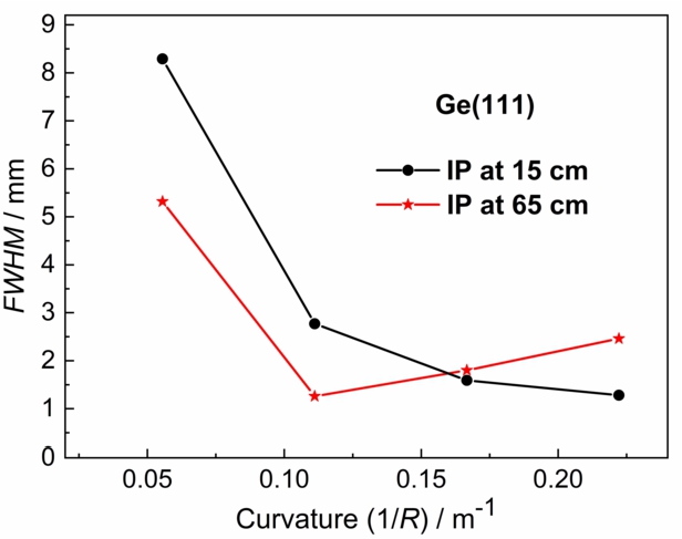
Similarly to the previous case, the same experimental investigation with the Ge(111) slab from the sandwich was carried out. Figure 10 shows several rocking curves of the Ge(111) slab with respect to the Si(111) one. On the other hand, Fig. 11 shows images of the profiles of the double diffracted beam as taken by IP at a distance of 15 cm and 65 cm from the second crystal. The dependencies in Fig. 12 summarize the focusing behavior of the beam for different crystal curvatures.
FWHM of the beam profiles vs the curvature of the Ge(111) slab imaged at the distances of 15 cm and 65 cm.
Examples of the profiles obtained by the diffraction on the α-Fe(211) polycrystalline pin of the diameter of mm for (a) – parallel setting and (b) – antiparallel setting. IP was at 45 cm from the α-Fe pin.
The FWHM dependence of the α-Fe(211) diffraction profiles on the Ge(111) curvature for both diffraction settings.
An inspection of Fig. 12 reveals that the focusing effect for smaller curvatures of the Ge(111) slab is evident. On the other hand, it can also be seen, that in the vicinity of the curvature 0.16 m−1, the monochromatic beam is highly parallel. Finally, the powder diffraction test was carried out on the 2 mm α-Fe(211) standard pin and some of the obtained results are shown in Fig. 13 and Fig. 14. It can be seen from Fig. 14 that for small (less than 0.6 m−1) of the Ge(111) slab the resolution represented by FWHM is nearly equivalent. The minimum FWHM for and settings in Fig. 13 provide an estimation of the FWHM() resolution roughly of about and , respectively.
Ge(311) crystal slab of the sandwich
Examples of the rocking curves of the Si(111) + Ge(311) setting for different radii of curvature of the second crystal – (a) and the dependence of the peak intensity of the rocking curve of the Ge(311) slab on its curvature – (b).
Images of the diffraction profiles taken at the distances of 15 cm (a,c,e,g) and 65 cm (b,d,f,h), respectively, for (a) and (b), (c) and (d), (e) and (f), (g) and (h); for the (Ge(311) slab.
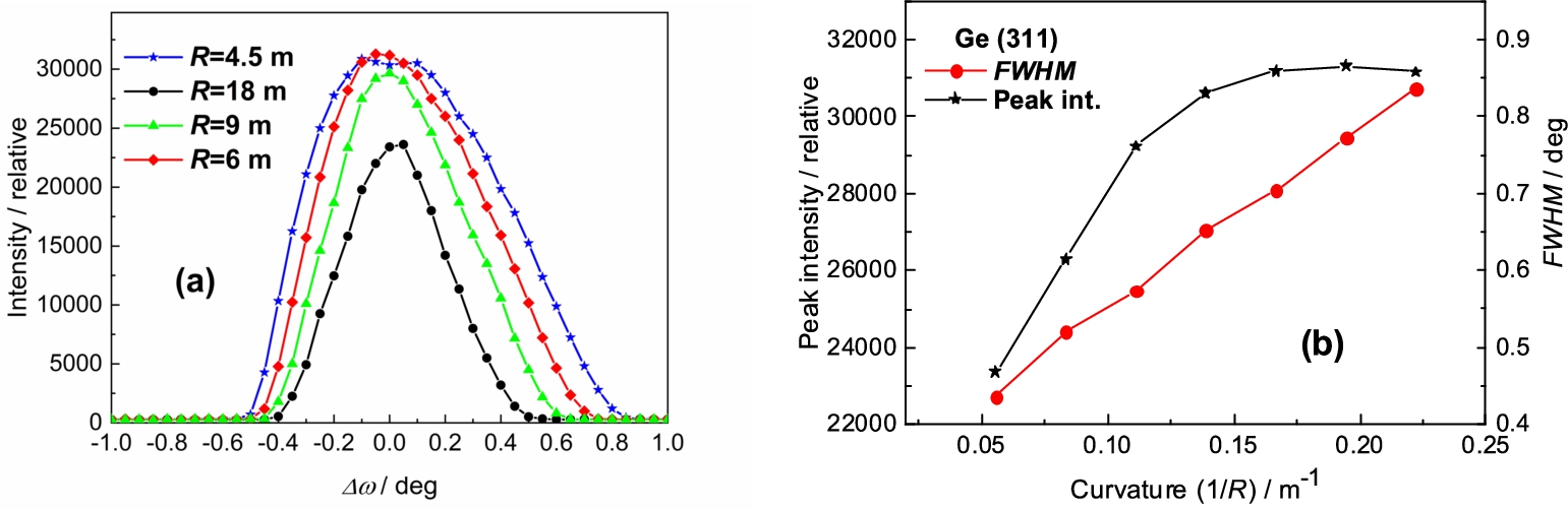
In this case, we used the third Ge(311) slab from the sandwich as the second crystal of the DC setting. By using the same experimental procedure as in the previous two cases, the luminosity of the setting was studied. Figure 15 shows the double-crystal rocking curves and the dependence of the peak intensity as a function of the curvature of the Ge(311) slab. The next Fig. 16 shows the images of the diffraction profiles of the double diffracted beam for for different curvatures at two distances from the second slab and Fig. 17 summarizes the focusing behavior of the beam for different crystal curvatures. Finally, the related powder diffraction tests for both parallel as well as antiparallel settings were carried out (see Figs 18 and 19). The distance of IP from the sample was 45 cm. The estimated resolution is slightly better than for the setting and about for the setting, respectively. Again, in the case of setting the diffracted beam from the sample can be considered quaziparallel.
FWHM of the beam profiles vs the curvature of the Ge(311) slab imaged at the distances of 15 cm and 65 cm.
Examples of profiles related to α-Fe(211) reflections obtained by diffraction on a standard polycrystalline pin of the diameter of mm for (a) – parallel setting, (b) – antiparallel setting.
The FWHM dependence of the α-Fe(211) diffraction profiles on the curvature of the Ge(311) slab for both settings.
Examples of the rocking curves of the Si(111) + Si(400) setting for different radii of curvature of the second crystal – (a) and the dependence of the peak intensity of the rocking curve of the Si(400) slab on its curvature – (b).
Si(400) crystal slab of the sandwich
Finally, the bent perfect Si(400) slab was tested for possible use in the dispersive DC monochromator setting. Figure 20 shows the DC rocking curves of the Si(400) slab with respect to the Si(111) one and the dependence of the peak intensity as a function of the curvature of the second slab. Then, Fig. 21 shows images of the profiles of the double diffracted beam at for different curvatures and two distances from the Si(400) slab. It can be seen from Fig. 20b that the intensity of the double diffracted beam increases with the crystal curvature and simultaneously for higher values of the curvature, the focusing effect is evident (see Fig. 22). The results of the powder diffraction test are shown in Figs 23 and 24 when the IP was situated at a distance of 45 cm. It can be seen from Fig. 24 that for a small curvature of the Si(400) slab, the resolution represented by FWHM is for nearly equivalent for both settings. The minimum FWHM in Fig. 24 is for () and provides an estimation of the resolution for and settings slightly better than (quaziparallel diffracted beam) and about , respectively.
Images of the diffraction profiles taken at the distances (a,c,e,g) – 15 cm and (b,d,f,h) – 65 cm, respectively, for (a) and (b), (c) and (d), (e) and (f), (g) and (h); for the Si(400) slab.
FWHM of the beam profiles vs the curvature of the Si(400) slab imaged at the distances of 15 cm and 65 cm.
Examples of the profiles related to α-Fe(211) reflections obtained by diffraction on a standard polycrystalline pin of the diameter of mm for (a) – parallel setting, (b) – antiparallel setting.
The FWHM dependence of the α-Fe(211) diffraction profiles on the curvature of the Si(400) slab for both settings.
Examples of the profiles related to α-Fe(110) reflections obtained by diffraction on a standard polycrystalline pin of the diameter of mm for (a) – parallel setting, (b) – antiparallel setting.
The FWHM dependence of the α-Fe(110) diffraction profiles on the curvature of the Si(400) slab for both settings.
In this case of the Si(400) slab, an additional powder diffraction test on the α-Fe(110) reflection was also carried out. The α-Fe(110) reflection is also very often used in the case of residual strain/stress measurements. Moreover, the related lattice spacing has the value very close to many other crystalline materials as e.g. γ-Fe(111), Cu(111), Ge(220), Ni(111) etc. which often appear in powder diffractometry. The obtained results are shown in Figs 25 and 26. It can be seen that an excellent resolution for both settings was simultaneously achieved for a rather strong crystal curvature. Furthermore, also in this case for small values of the curvature of the Si(400) slab (less than 0.06 m−1) the obtained monochromatic beam is highly parallel in the scattering plane and sufficiently wide for possible use in some high-resolution transmission experiments. This assumption has been was proven by observing the edge refraction effects on the teeth of a steel comb for the radius (see Fig. 27).
Photo of the teeth of a steel comb – (a) and the related edge refraction effects as taken by IP at a distance of 20 cm from the sample – (b).
Discussion
First, it is necessary to point out that in order to be able to use the DC setting as a neutron monochromator, only neutrons extracted from the polychromatic beam for of the rocking curve (peak intensity) are usable. The peak intensity is proportional to the area resulting from mutually overlapping of phase space elements of the individual BPC slabs. A comparison of the peak reflectivities of the individual BPC slabs of the sandwich (see Fig. 3) shows that thanks to a higher scattering amplitude of Ge with respect to Si, it would be more advantageous to use the Ge-slabs instead of the Si-slabs, namely, for stronger curvatures . As the peak reflectivity of the double-crystal setting is proportional to , the loss of intensity could be small if the curvature is not drastic.
An inspection of Figs 8, 14, 19 and 24 reveals that the best resolution in the powder diffraction tests on a α-Fe(211) standard sample is obtained at smaller curvatures below 0.125 m−1. There was also a little difference between the parallel and antiparallel settings that was observed. This property can be used successfully in the case of powder diffraction, namely, strain/stress measurements when two strain components can be measured simultaneously with an equivalent resolution as it is usually done in the case of the TOF method. This result can be expected, because for smaller curvatures of the second bent crystal the extracted monochromatized beam has a spread as well as a collimation smaller (a self-collimation effect). The excellent resolution property of the double diffracted beam can be used effectively in studies of microstrains as well as the grain size distribution in polycrystalline materials after applying shape analysis of the neutron diffraction peak profiles [2,3].
As to the spatial distributions of the double diffracted beams (see Figs 5, 11, 16 and 21 or Figs 6, 12, 17 and 22)) minimum FWHMs are observed at larger curvatures above 0.2 m−1, namely, for Si(220), Ge(311) and Si(400) slabs of the sandwich. As can be seen from the related figures, the focusing of the double diffracted beam is evident, while the peak intensity of the double crystal setting (for ) does not change significantly. Furthermore, focusing can be easily manipulated in a large range of curvatures. For strong curvatures, a high resolution in the powder diffraction experiment was achieved only for a parallel setting for Si(220), Si(400) and Ge(311) slabs from the sandwich, which means that the BPC slabs allowing for the setting to be sufficiently dispersive. However, it was not the case of the Ge(111) one having the value of the lattice constant close to that of Si(111). In the practical experiment a compromise in the choice of curvature should be made. As was demonstrated by the results in Figs 9 and 27 the double diffracted beams have very low divergence of about rad which makes it possible to use them for investigations e.g. of edge refraction effects. Particular studies with the dispersive double-crystal Si(220) + Si(311) and Si(111) + Si(311) settings containing the BPC Si(311) slab in strongly or fully asymmetric diffraction geometry can also be found in [12,13,19].
Rocking curves of the DC Si(111) + Si(220) setting with the sandwich containing 1, 2 or 4 slabs all of the thickness of 1.3 mm and bent with the radius of curvature – (a) and FWHM of monochromatic beam spatial distribution from the bent sandwich as a function of curvature taken at a distance of 70 cm from the sandwich [15].
In order to find the optimum performance of the diffractometer using a dispersive DC focusing monochromator, there are still some open questions which could be answered by means of Monte Carlo simulations [22]. Namely, the use of a thinner Si(111) crystal and optimization of the distance between the first and second crystal slab can open the door to obtaining a highly focused beam of submillimeter width at the focal point. On the other hand, with the use of thicker slabs some compromise between the slightly relaxed focusing as well as resolution and the instrument luminosity can be found as was pointed out in [15] (see an example in Fig. 28). Thus, the simulations can provide best possible resolution and luminosity properties of the optimized DC setting.
Finally, it can be stated that the presented dispersive DBC settings offer high-resolution monochromator alternatives to the conventional one, namely, for measuring the finer effects in powder diffractometry which can be successfully exploited at the high-flux neutron sources.
Footnotes
Acknowledgements
Measurements were carried out at the CANAM infrastructure of the NPI CAS Řež. P. Mikula and J. Šaroun acknowledge support from ESS participation of the Czech Republic – OP (CZ.02.1.01/0.0/0.0/16_013/0001794) and from the project ESS Scandinavia-CZ II (LM2018111), respectively. Furthermore P. Strunz and V. Ryukhtin acknowledge support from the Czech Academy of Sciences in the frame of the program “Strategie AV21, No. 23”. The authors thank B. Michalcová from NPI CAS for significant help with measurements and data elaborations.
V.Davydov, P.Lukáš, P.Strunz and R.Kužel, Single-line diffraction profile analysis method used for evaluation of microstructural parameters in the plain ferritic steel upon tensile straining, Materials Sc. Forum571–572 (2008), 181–188. doi:10.4028/www.scientific.net/MSF.571-572.181.
3.
R.Delhez, T.H.de Keijser and E.J.Mittemeijer, Determination of crystallite size and lattice distortions through X-ray diffraction line profile analysis, Fresenius’ Zeitschrift für analytische Chemie312(1) (1982), 1–16. doi:10.1007/BF00482725.
4.
V.T.Em, V.A.Somenkov, V.P.Glazkov, A.M.Balagurov, V.V.Sumin, P.Mikula and J.Šaroun, Residual stress instrument with double-crystal monochromator at research reactor IR-8, Physica B: Physics of Condensed Matter551 (2018), 413–416. doi:10.1016/j.physb.2018.02.042.
5.
ESRF Grenoble, ID 18 – Nuclear resonance beam line, https://www.esrf.fr/UsersAndScience/Experiments/MEx/ID18.
6.
Fixed-Incident-Energy Triple-Axis Spectrometer FIE-TAX at HFIRin ORNL, https://neutrons.ornl.gov/fietax.
7.
J.Kulda, A novel approach to dynamical neutron diffraction by a deformed crystal, Acta Cryst. A40 (1984), 120–126. doi:10.1107/S0108767384000271.
8.
J.Kulda and P.Mikula, A medium resolution double crystal diffractometer for SANS studies, J. Appl. Cryst.16 (1983), 498–504. doi:10.1107/S0021889883010894.
9.
P.Mikula, J.Kulda, P.Lukáš, M.Vrána and V.Wagner, Bent perfect crystals in asymmetric diffraction geometry in neutron scattering experiments, Nucl. Instrum. Methods in Phys. Res. A338 (1994), 18–26. doi:10.1016/0168-9002(94)90156-2.
10.
P.Mikula, J.Kulda, M.Vrána and B.Chalupa, A proposal of a highly efficient double crystal monochromator for thermal neutrons, J. Appl. Cryst.17 (1984), 189–195. doi:10.1107/S0021889884011274.
11.
P.Mikula, P.Lukáš and F.Eichhorn, New version of a medium resolution double-crystal diffractometer for the study of a small angle neutron scattering (SANS), J. Appl. Cryst.21 (1988), 33–37. doi:10.1107/S0021889887008653.
12.
P.Mikula, J.Šaroun, J.Stammers and V.Em, High resolution dispersive double bent crystal monochromators Si(111)+Si(311) and Si(111)+Si(400) with a strongly asymmetric diffraction geometry of the analyzer for powder diffractometry, Powder Diffraction34(S1) (2019), S18–S22. doi:10.1017/S0885715619000137.
13.
P.Mikula, J.Šaroun, P.Strunz and V.Ryukhtin, On possible exploitations of fully asymmetric diffraction (FAD) geometry of bent perfect crystals (BPC) for neutron monochromatization in diffraction instruments, Journal of Neutron Research22(1) (2020), 17–29. doi:10.3233/JNR-190122.
14.
P.Mikula and M.Vrána, New type of versatile diffractometer with a double-crystal (DC) monochromator system, Powder Diffraction30(Suppl. S1) (2015), S41–S46. doi:10.1017/S0885715614001201.
15.
P.Mikula, M.Vrána, J.Pilch, J.Šaroun, B.S.Seong, C.Woo and V.Em, Focusing and reflectivity properties of a parallel double bent crystal (+n,-m) setting, IOP Publishing Journal of Physics: Conference Series528 (2014), 012003. doi:10.1088/1742-6596/528/1/012003.
16.
P.Mikula, M.Vrána, J.Šaroun and V.Em, Neutron diffraction studies of a double crystal (+n,-m) setting containing a fully asymmetric diffraction geometry (FAD) of a bent perfect crystal (BPC), Powder Diffraction32(S1) (2017), S13–S18. doi:10.1017/S0885715616000725.
17.
P.Mikula, M.Vrána, J.Šaroun, V.Em, B.S.Seong and W.Woo, Double bent crystal dispersive arrangement for high resolution diffractometry, Journal of Physics: Conference Series340 (2012), 012014. doi:10.1088/1742-6596/340/1/012014.
18.
P.Mikula, M.Vrána, J.Šaroun, B.S.Seong and W.Woo, Double bent crystal monochromator for high-resolution neutron powder diffraction, Powder Diffraction28(S2) (2013), S351–S359. doi:10.1017/S0885715613000912.
19.
P.Mikula, M.Vrána, B.S.Seong, W.Woo, V.Em and D.Korytár, Neutron diffraction studies of a high resolution double crystal (+n,-m) setting containing Si(220) and Si(311) bent perfect crystals in symmetric and fully asymmetric diffraction geometry, respectively, IOP Publishing Journal of Physics: Conference Series528 (2014), 012004. doi:10.1007/978-3-540-74561-7_4.
20.
M.Popovici and W.B.Yelon, Design of microfocusing bent-crystal double monochromators, Nucl. Instrum. Methods in Phys. Res. A338 (1994), 132–135. doi:10.1016/0168-9002(94)90173-2.
21.
M.Popovici and W.B.Yelon, Focusing monochromators for neutron diffraction, J. Neutron Research3(1) (1995), 1–25. doi:10.1080/10238169508200187.
22.
J.Šaroun and J.Kulda, Raytrace of neutron optical systems with RESTRAX, in: Modern Developments in X-Ray and Neutron Optics, A.Erko, M.Idir, T.Krist and A.G.Michette, eds, Springer Series in Optical Science, Vol. 137, Springer, Berlin, Heidelberg, 2008, pp. 57–68. doi:10.1007/978-3-540-74561-7_4.
23.
J.Šaroun, P.Lukáš, P.Mikula and B.Alefeld, Optimization of a double bent crystal diffractometer for neutron small-angle neutron scattering experiments, J. Appl. Cryst.27 (1994), 80–88. doi:10.1107/S0021889893006831.