
Abstract
The general control system (GCS) in the Materials and Life Science Experimental Facility (MLF) at the Japan Proton Accelerator Research Complex (J-PARC) has a data storage (DS) server that stores operational data on the status of neutron and muon targets in the MLF. It has worked well to detect unusual situations around these target stations and to investigate the causes of accidents by checking data in the DS server for short-term operations. To pick up potential abnormalities in the slight state transitions from the target stations, however, it is necessary to introduce an abnormality sign determination system (ASDS). This ASDS requires an integral data storage (IDS) server that stores various operational data throughout the proton beams, target stations, and secondary beams for long-term operations because it judges potential abnormalities by using algorithms based on analysis of these data. This report describes a present status of the GCS, a conceptual design for the ASDS, and the installation of the IDS server.
Keywords
Introduction
The Materials and Life Science Experimental Facility (MLF) at the Japan Proton Accelerator Research Complex (J-PARC) generates pulsed muon and neutron beams by injecting highly intense proton beams from accelerators through a 3 GeV proton beam transport line (3NBT) into graphite and mercury targets. Then, it supplies the muon and neutron beams to user apparatuses located in two experimental halls of the MLF, as shown in Fig. 1 [6]. To operate the target stations safely and efficiently, a general control system (GCS) operates within the MLF [2,8,10,11,14]. The GCS administers operation processes and interlocks for many instruments for various statuses, such as beam irradiation, target maintenance, and emergencies. Although the GCS is an independent system that controls the target stations, it works closely with the control systems of the accelerators and other facilities through a central control building (CCB) at the J-PARC.
The GCS has managed an exclusive data storage (DS) server to store operational data, such as temperatures, pressures, and the flow rates of instruments, every several seconds around the target stations, as shown in Fig. 1. It has functioned well to monitor the status, detect abnormal events, and investigate unexpected behaviors in the target stations by checking data during comparative short-term operations. It has contributed significantly to investigating behavior and damages of the target stations during the Great East Japan Earthquake [12]. Moreover, diagnostic devices such as a mercury target diagnostic system and neutron detector systems shown in Fig. 1 have worked for checking individual soundness. For example, pressure waves generated by proton beam injections into the mercury target cause pitting damages on an inner surface of the target vessel [3,5]. The mercury target diagnostic system composed of a laser interferometer and an acoustic measurement device has monitored influences of the pressure waves as vibration signals for evaluating the pitting damages. While, the neutron detector systems have measured such as neutron beam intensity and energy spectrum on a regular basis for checking performance of neutron moderators, reflector, etc.
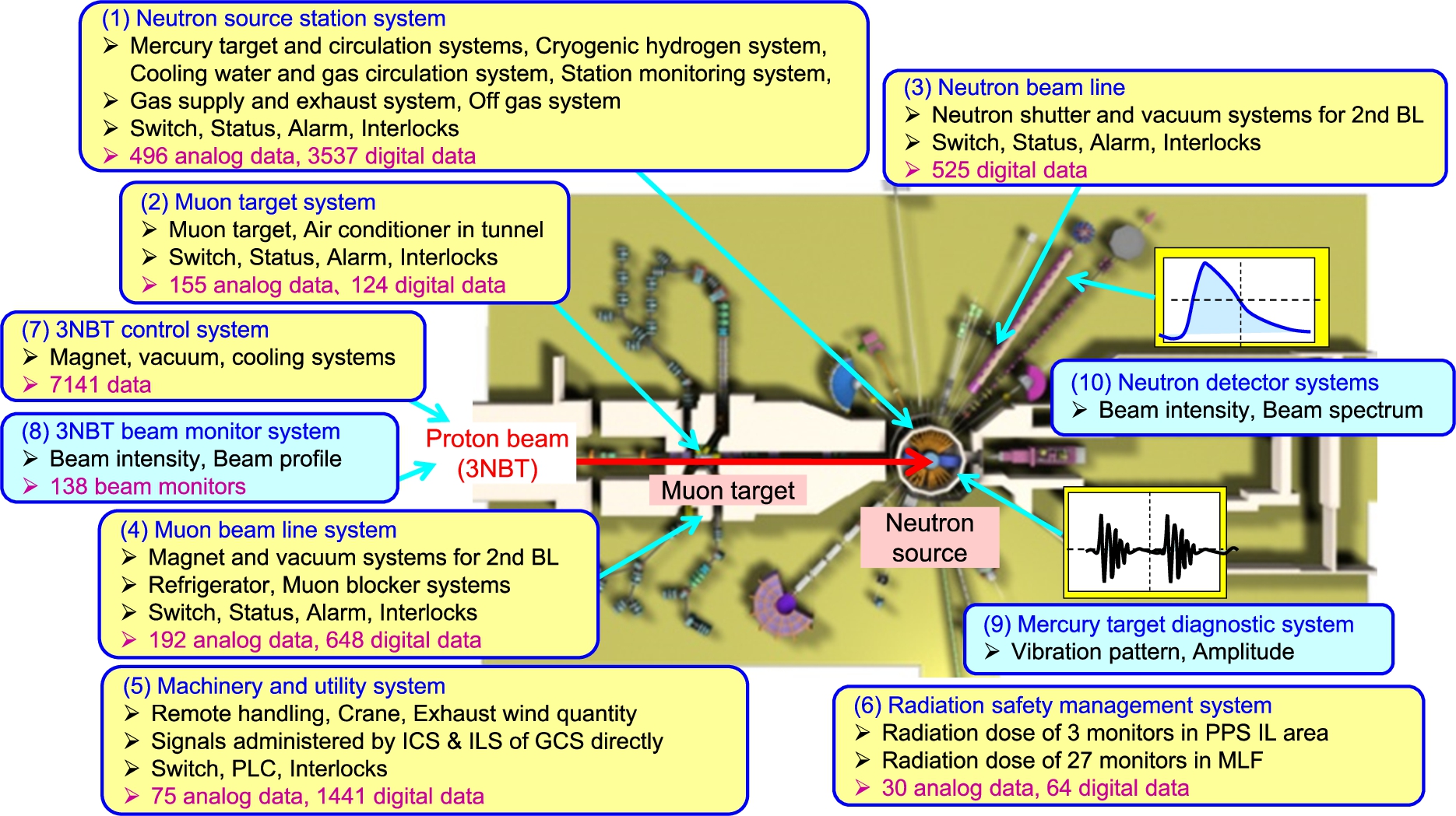
Sketch of the Materials and Life Science Experimental Facility (MLF): in the MLF, operational data for various instruments are dealt with by their instrument control systems. Over 900 analog and 6300 digital data from the (1) neutron source station system, (2) muon target system, (3) neutron beam line system, (4) muon beam line system, (5) machinery and utility system and (6) radiation safety management system, are stored in the DS server of the GCS. The GCS also operates as communicating with the (7) 3NBT control system and (8) 3NBT bean monitor system. In addition, diagnostic devices such as the (9) mercury target diagnostic system and (10) neutron detector systems work for checking individual soundness.
However, the proton beam power for user beam operation has reached to 0.5 MW in 2018, and it will ramp up to 1MW within several years. In high power operations, deteriorations caused by pitting damage, radiation damage, thermal fatigue, etc. and activations in the target stations become more serious because they will progress rapidly, and unexpected breakages might occur in the target stations. For preventing troubles related to the target stations from expanding to become serious, we considered that introduction of an abnormality sign determination system (ASDS) would be necessary to pick up potential abnormalities in the target stations as early as possible. The ASDS is expected to judge potential abnormalities in real time via slight state transitions in the target stations by using algorithms based on analysis of various operational data during long-term operations. As the one of the key devices for realizing the ASDS, it requires an integral data storage (IDS) server that can deal with various data throughout the proton beams, target stations, and secondary beams, which are usually saved an individual storage device in a different data format. This report describes the present status and upgrade history of the GCS, the concept of ASDS, and installation of the IDS server.
Outline of the GCS
Figure 2 shows the overall structure of the GCS from the CCB to instruments within the MLF. The GCS consists of several subsystems in accordance with their role, such as an integral control system (ICS), interlock systems (ILS), shared servers, a network system (LAN), and a timing distribution system (TDS) [14]. They comprise personal computers (PCs), programmable logic controllers (PLCs), and exclusive modules, such as monitor and operation (MO) PCs, database (DB) servers, general control panels (GCP), and local control panels (LCPs). They are connected through optical cables for PLC links and Ethernet and metal cables.

Overall structure of the general control system (GCS) and the data transmission route from the instrument control systems.
The ICS operates many instruments such as the target trolley, muon rotating target, and mercury circulation systems through about 40 LCPs and the remote input/output panels (IOP) under the PLC link from the MO PCs and the DB serves in the MLF control room located on the third floor of the MLF building. The remote IOPs which have various communication conversion modules, enable to communicate with independent control systems such as the PPS directly. The shared servers comprise server PCs, such as DS, web distribution (WD), and monitoring camera servers. They acquire, arrange, store, display, and distribute operational information. The ICS and servers are designed based on an experimental physics and industrial control system (EPICS) as framework software, and a control system studio as a user interface window that considers data transmission based on the cannel access (CA) protocol of EPICS with other facilities in J-PARC [9,14]. The MO PCs are installed in a control system studio (CSS) software as an operator interface (OPI) of EPICS, and the DB server functions as an input/output controller (IOC) which enables data communication between EPICS OPI and PLCs.
The ILS administers three kinds of interlock systems, called the machine, target, and personnel protection systems (MPS, TPS, and PPS) [13]. The MPS is a system for preventing trouble in important machines due to unusual irradiations by prohibiting proton beam injections. The PPS is a system for preventing exposure of personnel to high radiation. They safely administer many instruments and high radiation areas, work closely with the interlock systems of the accelerators and other facilities through the CCB of the J-PARC, stop beam injections if necessary, and maintain safety in MLF in emergencies.
The network systems of the GCS comprise a control LAN (C-LAN) to control the accelerator and facility and a LAN for users and user experimental apparatuses in J-PARC, denoted JLAN. The C-LAN is connected to the JLAN from the CCB through a firewall. The WD server distributes operational information, such as operational status, beam power, and beam trend, to users through information displays connected to the C-LAN, and the authorized PCs connected to the JLAN in the form of a Web browser. In the J-PARC, a scheduled timing system based on high-precision master clock signal is adopted as a standard timing system. It plays important roles to control distribution patterns of the beam pulses from the accelerators to each facility. In MLF, the TDS distributes the scheduled timing signals to the instruments which operate in synchronizing with beam injection at a frequency of 25 Hz [11,13]. In addition, the TDS also distributes the trigger signals in synchronizing with primary beam injections directly such as current transformer signals of the 3NBT.
Many upgrades have proceeded in the entire GCS during the ten years after the end of its construction in June 2007. Table 1 shows the upgrade history of the GCS between 2007 and 2018 (fiscal year). This period could be classified into three stages of “commissioning on operation and control” between 2007 and 2009, “modification for sustainable long-term operation” between 2010 and 2015, and “replacement of instruments” after 2016. Since the first beam injection in May 2008, significant upgrades have been carried out in the MLF, such as installations of a micro bubbler for mitigating the pitting damages by suppling bubbling gas into the mercury target vessel [3,5], a unified Hg-target active monitor (UHAM) for detecting a radioactive gas leakage from the target station, and a muon rotating target for extending its lifetime [4], to prepare to ramp up the proton beam power. User experimental PPS areas have also increased from the five areas at the first beam injection to 27 areas at present. During these annual incremental upgrades to the target devices and user experimental apparatuses, the GCS has operated stably without any serious troubles after modification based on commissioning for operation and control of the entire MLF during stage 1 [11,14].
For sustainable long-term operation and maintenance, significant improvements in the GCS were performed during stage 2 [14,15]. For examples, the previous ICS was designed based on the iFIX-supervisory control and data acquisition (SCADA), as framework software. The DS and WD servers were also installed in software compatible with the iFIX-SCADA. In order to improve maintenance flexibility, however, the upgraded GCS based on EPICS has been developed and replaced until March 2015 completely. In 2013, the risk management system for the J-PARC was re-examined after occurring an incident of the radioactive material leakage at the J-PARC hadron experimental facility. The ICS and ILS of the GCS were also modified based on this re-examination, where it was recommended that the status of radiation dose shown in Fig. 1 would be monitored on the ICS MO system with those of the target stations for checking abnormalities integrally. Then, the data of the radiation safety management system which has worked usually as an independent system could be stored in the DS server by introducing a relay PLC-CPU module which could function as the EPICS-IOC. During stage 3, many instruments in the GCS have been replaced to the latest models because support from the manufacturers was ending.
Upgrade history of the GCS
Upgrade history of the GCS
In the stages so far, function of the GCS to monitor and detect abnormal events has been upgraded gradually as expanding the data dealt with the DS server. Moreover, diagnostic devices such as the mercury target diagnostic system have also worked independently in the MLF. Under ramping up proton beam power to 1MW within several years, however, the deteriorations and activations in the target stations will progress rapidly, and unexpected breakages might occur in the target stations. For preventing troubles from expanding to become serious, we planned to introduce the ASDS which would judge potential abnormalities as early as possible by using the data transmitted from various storage device in the next stage.
Figure 2 also shows the data transmission routes from the instrument control systems to the current DS server. In the MLF, there are two types of instrument control systems. One is a slow control system that transmits operational data every several seconds, and the other is a fast control system that transmits data by synchronizing with the beam injection at a frequency of 25 Hz. The DS server stores operational data about the instrument status of the target stations, such as temperature, pressure, flow rate, and liquid level. These data are transmitted from slow control systems, such as the (1) neutron source station system, (2) muon target system, (3) neutron beam line system, (4) muon beam line system, (5) machinery and utility system, and (6) radiation safety management system, as shown in Fig. 2. To enable data transmission by the CA protocol of EPICS, a Postgres-SQL operates within the DS server as relational database (RDB) software. Over 900 analog and 6300 digital data shown in Fig. 1, are transmitted from the LCPs through the PLC link and converted to EPICS record format by the DB server, as shown in Fig. 2. Then, the analog data are stored in the DS server every several seconds, and digital data is stored individually when it changes.
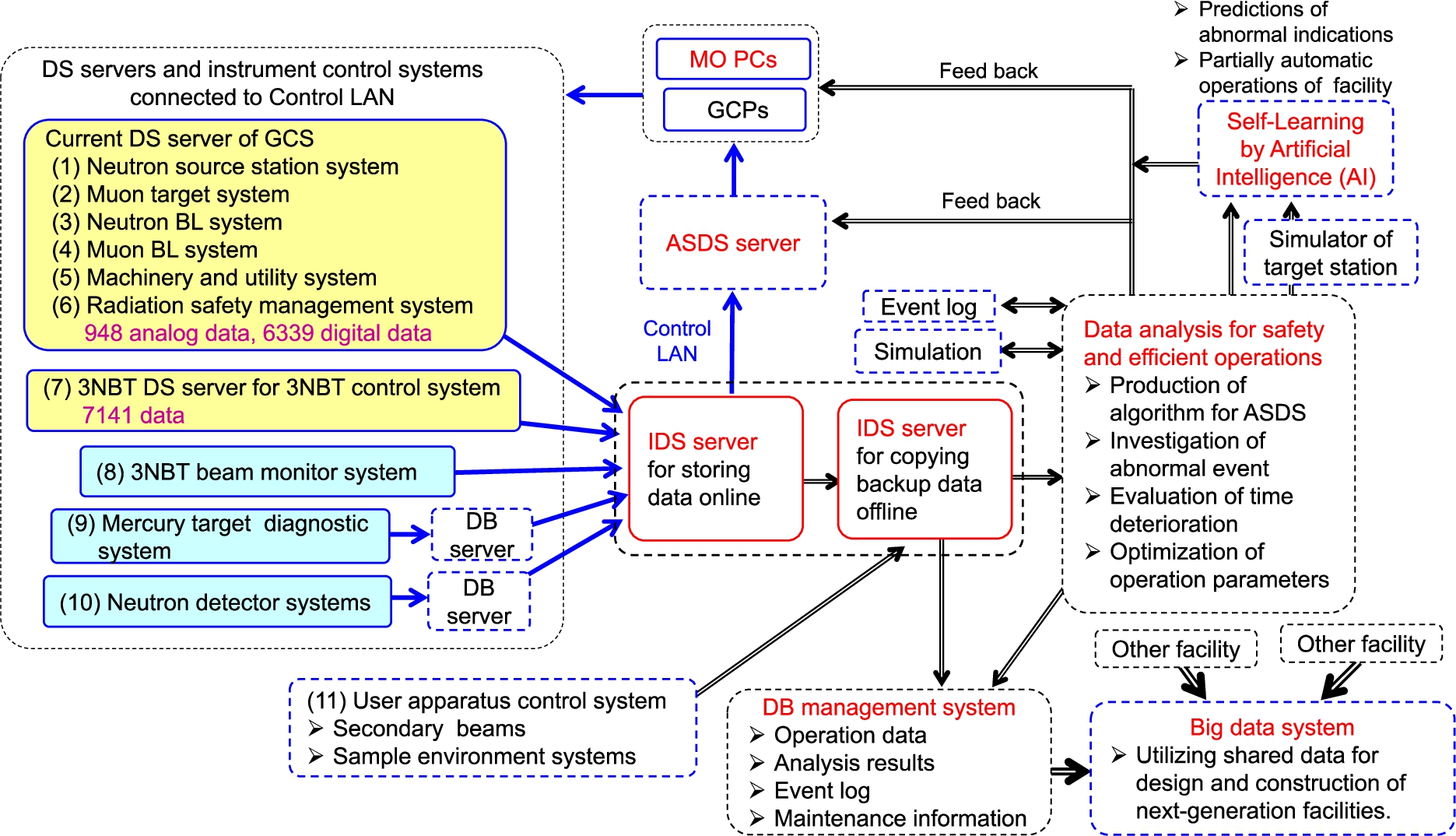
Sketch of the data flows with a focus on the abnormality sign determination system (ASDS) and integral data storage (IDS) server.
Figure 3 shows a sketch of the data flows with a focus on the ASDS and IDS servers. The IDS server consists of online and offline servers, as shown in Fig. 3, and operates as an independent system in contrast with the current DS server and instrument control systems. The online IDS server stores the data that are transmitted both from fast and slow control systems throughout the proton beams, target status, and secondary beams in common data format. These data in the online IDS server are copied as backup data into the offline IDS server periodically. They are utilized to develop algorithm programs to investigate abnormal events, evaluate time deteriorations for upgrading instruments, and optimize parameters for effective operation and maintenance by combining with simulations. The results of the offline analysis are fed back to the ASDS server, which judges abnormality using online data and the MO PCs and GCP, which control the instruments of the target stations integrally. In the future, an artificial intelligence system (AIS) that has self-learning functions will execute the offline data analyses to predict unanticipated abnormal indications and achieve partially automatic operations of the facility. For supporting the judgments of the AIS, a simulator that predicts operation statuses of the target stations, such as temperature, pressure, and flow of liquid and gas circulation systems, will be also developed upon considering the results of the offline analysis.
As the first step to realize the ASDS, an IDS server prototype, which consists of online and offline servers, was developed to examine specification of the IDS server. Both servers have 10 terabyte hard disks with redundancy via RAID 1 and Postgres-SQL software to communicate via the CA protocols of EPICS. Archive engine software for EPICS also operates within the online IDS server and functions to acquire operational data, including over 7000 pieces of data from the current DS server and over 7000 pieces of data from the 3NBT instruments, such as the magnet and coolant systems from the (7) 3NBT DS server shown in Fig. 2, every several seconds. In addition, it also communicates with seven control systems that manage over 130 beam monitors of the 3NBT, shown as the (8) 3NBT beam monitor system in Fig. 2 and Fig. 3, and acquires data on the proton beams at a frequency of 25 Hz [6,7]. The data stored in the online IDS server are copied as backup data into the offline server periodically.
Trial operation of the prototype has occurred since April 2019 to evaluate its performance, including data transmission speed, storage capability, long-term stability, and reliability of the systems. In addition, the backup data stored in the offline IDS server will be utilized to develop algorithm programs to evaluate radiation damages, time deteriorations, and so on.
Summary
In this report, we explained the present status of the GCS, its upgrade history, and the concept of the ASDS. The ASDS will judge potential abnormalities in real time by picking up slight state transitions in the target stations according to observational and data analysis. For the next stage during ramping up the proton beam power to 1 MW, it will be expected to pick up abnormalities caused by the pitting damages of the target vessel, burning phenomena of the moderator materials, etc. for estimating the lifetimes of components of the target stations. We also developed a prototype IDS server for the ASDS.
In addition to storage of data from the DS server, 3NBT DS server, and 3NBT beam monitor systems, it is desirable to store data from other fast control systems, such as the (9) mercury target diagnostic system [3,5] and the (10) neutron detector systems for the ASDS, as shown in Fig. 2 and Fig. 3. For the purposes, we will develop the DB servers that enable to convert their data to the EPICS record as shown in Fig. 3. It will be possible because interface devices functioning as the EPICS-IOC for them are supported already.
It is also necessary to establish the procedures of offline data analysis. The AIS is expected to be useful for the offline data analysis in addition to a numerical analysis. At present, the pitting damages are evaluated with the numerical analysis by combining the data of the vibration signals caused by the pressure waves, beam power, beam profile, mercury flowrate, etc. As the first trial of AIS application, we plan to predict the vibration signal patterns from various operational data by applying deep learning flame work software such as Chainer [1], and to detect unexpected behaviors by picking up the slight state transitions from the predicted signal patterns. In the future, operational data within the MLF may be shared with those of other similar facilities through an authorized internet network system used by several target station facilities. These shared data will be useful for design and construction of next-generation facilities.
Footnotes
Acknowledgements
The authors are grateful to Dr. M. Futakawa, Dr. H. Takada, the members of Neutron Source Section and the staffs of J-PARC Center for their useful help and suggestions.