We investigated neutron flux at a sample position and energy resolution of a direct-geometry disk-chopper spectrometer AMATERAS under various chopper conditions and compared them with simulations and calculations. The measured flux was comparable to that of similar high-flux spectrometers. The resolution when using a pulse-shaping chopper correlated well with the analytical calculations, including the thickness of the disk chopper, the sample size, and the penetration depth into the detector. The results show that the chopper, placed at the intermediate distance of the primary spectrometer, functions as a pulse shaper that optimizes the flux and resolution below the incident energy of 10 meV.
AMATERAS is a direct-geometry disk-chopper spectrometer at the Materials and Life Science Experimental Facility (MLF) at the Japan Proton Accelerator Research Complex (J-PARC), covering the cold to subthermal neutron energy range [10–14]. The spectrometer is suitable for measuring collective excitations such as magnons and phonons and investigating relaxation phenomena in disordered systems. Various materials can be a measurement target for AMATERAS, as with other similar spectrometers such as IN5 at ILL [16], LET at ISIS [1], and CNCS at SNS [2].
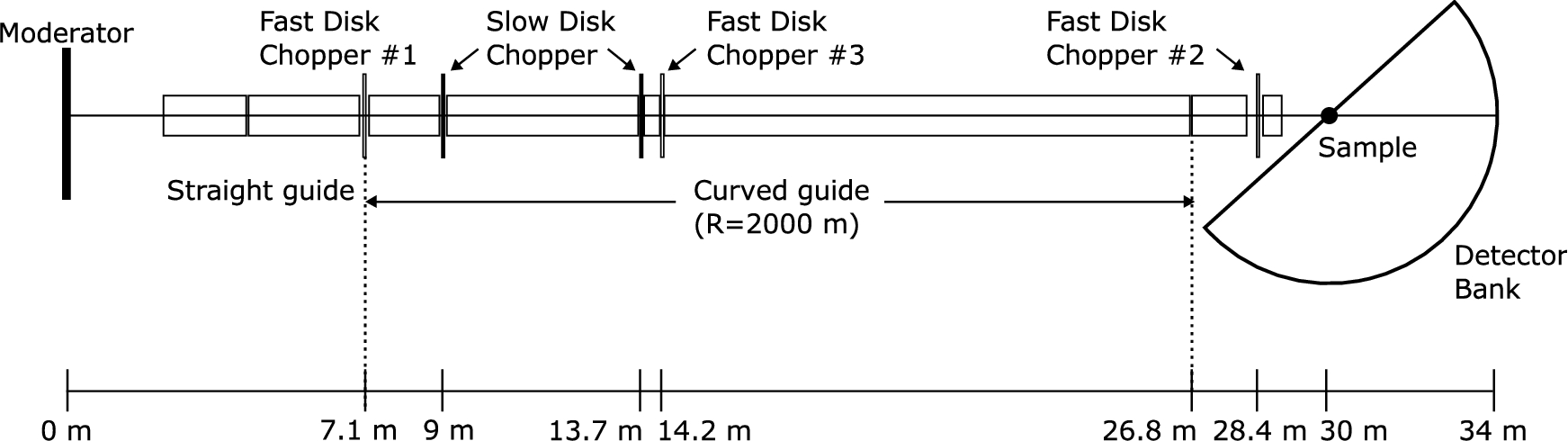
AMATERAS is at beamline 14 with a coupled moderator. The primary spectrometer, with a flight path of 30 m, comprises five choppers and a supermirror guide (Fig. 1). Three fast disk choppers, #1, #2, and #3, are used for pulse shaping, monochromator, and contamination and frame-overlap removal, respectively. Choppers #1 and #2 are counter-rotating double-disk choppers, and #3 has a single disk. Chopper #2 has two slits, 10 mm and 30 mm wide, to allow flexible energy resolution selection, and #1 and #3 have 30 mm slits. Measurements with multiple incident energies () can be carried out on AMATERAS by using a repetition rate multiplication (RRM) technique [9,15,17], enhancing measurement efficiency. The slow disk choppers running at 25 Hz determine the range of .
Schematic layout of AMATERAS (top view).
Since its operation in 2009, many experiments have been conducted on AMATERAS. In actual experiments, between 2 and 20 meV are typically used. In this paper, we report the neutron flux and energy resolution of AMATERAS for chopper conditions typically used in actual measurements.
Neutron flux at sample position
Measured and simulated flux of (a) monochromatic and (b) white neutrons at the sample position against the incident energy. The kink at 4–5 meV in the measured flux is due to the Bragg edge of aluminum existing on flight path.
We measured the neutron flux of monochromatic neutrons at the sample position using a gold foil and a vanadium plate of 100 mmW × 100 mmH × 0.1 mmt and 100 mmW × 100 mmH × 0.3 mmt, respectively, which are much larger than the beam size. The gold foil measurement was performed with a single (10.5 meV), and the vanadium measurement with multi- (2.6, 3.8, 5.9, 10.5, and 23.7 meV). For both measurements, chopper #2 was used with 150 Hz, and choppers #1 and #3 were stopped. The number of incident energies was determined by the slow disk choppers. Fluxes under conditions using multiple fast disk choppers are shown in Section 3. The samples were placed so the thickness direction was perpendicular to the incident beam. The incident beam at the sample position was approximately 10 mmW × 20 mmH. The beam power was 817 kW. Corrections due to neutron absorption in vanadium, detector efficiency, and solid angles were accounted for. The flux of the white beam was estimated using hollow cylindrical vanadium (, ).
Figure 2(a) and (b) show the neutron flux of monochromatic and white neutrons against the incident energy. The neutron fluxes at evaluated by the gold foil and the vanadium were similar (). The statistical error of the vanadium measurements was less than 1%. The estimate of the irradiated area of the sample contains an uncertainty of a few percent. The value is comparable with other high-flux disk-chopper spectrometers, such as CNCS [2] and IN5 [16], for similar energy resolutions. The simulation performed with the McStas package [8,18,19] is also shown in the plots. The measured flux is approximately 1/3–1/4 of the simulated flux for monochromatic and white neutrons, and the difference becomes more significant at higher . The discrepancy is significantly larger than those for other instruments at MLF, which are within 50% [4,5]. The reason for the discrepancy between observation and simulation is unknown, but the reflectivity and the critical angle of the Ni–Ti supermirror might be lower than the nominal values. The actual reflectivity is currently under investigation, and the issue will be resolved in the future.
Energy resolution and flux for typical chopper conditions
The energy resolutions under typical chopper conditions were estimated using a hollow cylinder vanadium sample (, ). Table 1 summarizes the chopper conditions. For conditions 1, 2, and 2’, only chopper #2 is used, therefore, the pulse is not shaped. For condition 3, #3 is used as a pulse-shaping chopper. For conditions 4 and 4’, #1 is used as a pulse-shaping chopper with a single disk, and #3 is employed as a contamination-remover. The slit width of chopper #2 is 30 mm for conditions 1–4, and 10 mm for conditions 2’ and 4’. Note that the slow disk choppers are running in all the listed conditions.
The elastic energy resolution of a chopper spectrometer with a pulsed neutron source is described as [6,13,20]
, , and are the distances from the moderator to the sample, the sample to the detector, and the monochromatic chopper to the sample, respectively. For AMATERAS, , , and . , , and are the aperture times of the monochromatic chopper, the time width of the pulse at the moderator position, and the time of flight (ToF) from the moderator to the monochromatic chopper, respectively. is the primary energy resolution source and is defined as
where w is the slit width (10 mm or 30 mm), is the effective slit width, R is the radius (300 mm at the center of the beam), d is the thickness, and f is the rotation frequency for chopper #2. is the velocity of the incident neutron. The coefficient 1/2 in Eq. (2) is due to the double disks counter-rotating.
Equation (3) indicates that the effective slit width decreases by the distance the disk moves while the neutrons pass through it. Consequently, becomes shorter. This effect is significant at low and for the 10 mm slit.
Typical chopper conditions
Conditions
(Hz)
(Hz)
(Hz)
Slit width (mm)
1
—
150
—
30
2
—
300
—
30
2’
—
300
—
10
3
—
300
150
30
4
300
300
150
30
4’
300
300
150
10
Without the pulse shaping, a time spread due to the moderator () [3] is used as . dependent on ; lower the is, larger the becomes. When the pulse-shaping chopper is operated, the effective time width can be employed [13]. If is well shorter than , is described by
and are the opening time of the pulse-shaping chopper and the distance from the moderator to the pulse-shaping chopper, respectively. For AMATERAS, (chopper #1) and (chopper #3). When , is unaffected by the pulse-shaping chopper. In the calculation, the shorter one should be chosen.
For , rotating chopper #3 at 150 Hz does not affect the energy resolution because is longer than . For instance, for with 30 mm slit, , (#1, 300 Hz), and (#3, 150 Hz).
The elastic energy resolutions under (a) nonpulse-shaping conditions and (b) pulse-shaping conditions; the symbols show the observed values, the curves show the calculation using Eq. (1), and the asterisks show the simulated values; the arrows show the energies where .
is the uncertainty of described by , where and are the uncertainties derived from the sample and the detector, respectively. For cylindrical samples, , where is the sample diameter [6]. is the penetration depth of the neutron into the 3He detector estimated by considering the detector geometry (25.4 mm diameter). is 6.7–8.3 mm for . and are calculated only in the horizontal plane, and the elevation direction is not considered.
is dominant because is approximately six times larger than . For lower , is longer, and the contribution of increases. Using a pulse-shaping chopper, the becomes shorter and almost constant, decreasing the contribution. The contribution of is significant for lower and shorter because is almost independent of and the slit width, unlike the other contributions. For example, the contribution of is 18% (2 meV) and 3.3% (20 meV) for condition 4 with the 30 mm slit, and 45% (2 meV) and 17% (20 meV) for condition 4’ with the 10 mm slit.
Figure 3 shows the measured, calculated, and simulated energy resolutions. The calculated resolutions were obtained using Eq. (1). The simulated results were the values obtained by McStas with the contribution added. For the nonpulse-shaping conditions (conditions 1 and 2), the measured resolutions are significantly worse than the calculated values, while the simulated values roughly reproduce the measured values (Fig. 3(a)). The difference is due to the non-Gaussian pulse shape. Since Eq. (1) assumes a Gaussian distribution for each component, it no longer holds for non-Gaussian components. The energy spectra in conditions 1 and 2 exhibit a tail in the neutron energy gain side () and deviate considerably from the Gaussian shape (Fig. 4(a) and (b)). We verified our considerations by calculating an energy spectrum convoluted with the actual pulse shape and triangular chopper aperture (Fig. 5(a)). Figure 5(b) shows the spectrum where the contribution is included. The calculated spectrum reproduces the actual measured one well.
Energy spectra of vanadium taken with and 23.7 meV under (a) and (b) nonpulse-shaping and (c) and (d) pulse-shaping conditions; the curves represent Gaussian fits to the elastic signals.
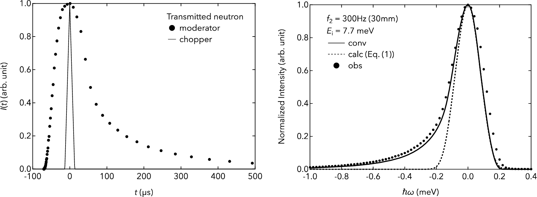
(a) Transmitted neutrons at the moderator, chopper, and (b) energy spectra, for and the 30 mm slit; the solid curve is the convolution of the pulse profile at the moderator and the aperture function of the chopper; the dashed curve is the profile calculated by Eq. (1).
Figure 3(b) shows the energy resolutions with pulse-shaping (conditions 3, 4, and 4’). The arrows indicate the where . At higher (), a difference exists between the measured and calculated resolutions because is too short for the pulse-shaping chopper to shape the neutron pulse. The spectral shape deviates from the Gaussian (Fig. 4(d)). At lower , the pulse shape is almost Gaussian (Fig. 4(c)), and the energy resolutions can be approximately described using Eq. (1). With the 30 mm slit, when chopper #3 is employed as the pulse shaper (condition 3), the measured resolutions are in close agreement with the calculations using . Chopper #3 with 150 Hz would make the pulse shape closer to Gaussian rather than reducing the pulse width. As a side note, the pulse width can be slightly reduced when chopper #3 is rotated at 300 Hz. Meanwhile, chopper #1 (condition 4) improves the energy resolutions below 3 meV, although the measured values are slightly greater than the calculations using . The contribution from increases as decreases because does not depend much on . For the 10 mm slit (condition 4’), the measured and calculated resolutions correlate well. The chopper opening time is approximately 1/3 of that for the 30 mm slit (condition 4), but the actual resolution is approximately 1/2 due to the contributions from and .
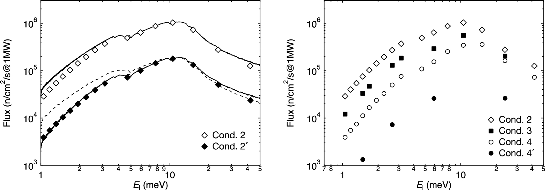
Figure 6 shows the measured flux for various chopper conditions. The flux exhibits a maximum at approximately 10 meV. Figure 6(a) shows the flux without the pulse shaping for the 30 mm (condition 2) and the 10 mm (condition 2’) slits. The difference between conditions 2 and 2’ increases as decreases because of the effect of . The solid curves represent the energy profiles of the white beam multiplied by and reproduce the measured monochromatic flux. The profile without the multiplication is plotted as a dashed curve for comparison. The effect of is more significant for lower . For the 10 mm slit, for , and the intensity becomes 40% of the intensity without considering . Figure 6(b) shows the flux with pulse shaping (conditions 3 and 4), with the data without it (condition 2). The pulse shaping reduces the flux for (). The use of chopper #1 further decreases the neutron flux. For , the contribution of is not so large, and the resolution improvement is slight (Fig. 3(b)). Therefore, using chopper #1 in this energy region is not so beneficial. In other words, it proposes that chopper #3 works well as a pulse shaper. For the 10 mm slit (condition 4’), the flux drastically decreases from that of the 30 mm slit (condition 4). Given the slit size ratio (=1/3), the flux ratio would be 1/9, but it is approximately 1/7.
The measured flux of monochromatic neutrons taken with (a) conditions 2 (30 mm slit), 2’ (10 mm slit), and (b) 2, 3, 4 (30 mm slit), and 4’ (10 mm slit); the solid and dashed curves in (a) are the profile of the white neutrons multiplied by and not multiplied, respectively, where scale factors are multiplied to match the value of monochromatic flux at 10 meV.
We comment on the optimization of multi- measurements. Optimizing the chopper phases is necessary to maximize the flux. The displacement of the disk position has a severe impact for the flux. When the disk position is displaced from the ideal place, the disk phase should be adjusted to pass the neutrons with the expected energy. A double-disk chopper should have a gap between the disks, so the chopper phase cannot be optimized simultaneously for neutrons with different velocities. The effect of the double disk is significant when the chopper is placed close to the moderator because the deviation from the ideal ToF at the chopper is proportional to , where a is the gap size and L is the distance between the moderator and the chopper. Thus, using the double disk of chopper #1 is impractical for the multi- measurements. The delay of pulse at the moderator has a similar effect. The delay time is 30–120 for . When the wide range of is used, this effect can cause a problem in optimization but is less severe than the gap between the disks.
In actual experiments at AMATERAS, the multi- measurements are typical, and chopper #1 is operated with a single disk. Chopper #1 is frequently not used, and #3 is employed as the pulse shaper instead, especially for samples with weak scattering signals. It has been considered that three sets of fast disk choppers are required for the RRM technique to prevent spurious neutrons from leaking through the choppers, originating from the long tail of the pulse source [9]. However, practically, these leaks seldom lead to significant problems, even if chopper #1 is not used, as they rarely result in spurious peaks within the typically employed energy transfer range (<0.8 ). Chopper #1 can be used to improve resolution below or to make pulse shape symmetrical in exchange for neutron flux; it is typically used for QENS measurements of hydrogen-containing materials. The high-resolution experiment using the 10 mm slit is few; it is sometimes used in experiments requiring high energy resolution in a high-Q region.
Summary
We measured neutron flux using Au foil and V plate and performed a Monte Carlo simulation using McStas for the AMATERAS spectrometer. The flux obtained from the Au and V measurements correlated well with each other. The measured flux is comparable with that of other disk-chopper spectrometers with high flux at similar energy resolutions. However, the simulated flux is approximately 3–4 times larger than the observed one. This issue is currently being addressed.
The energy resolutions and the flux under various chopper conditions were also investigated and compared with the analytical calculations where the disk chopper thickness, the sample size, and the penetration depth into the detector were considered. Without the pulse shaping, the energy resolution is worse than the calculation due to the non-Gaussian shape of the original pulse. The pulse-shaping chopper can provide Gaussian-like spectra at lower where the aperture time of the chopper slit is shorter than the pulse width. Chopper #3, placed at the intermediate distance of the primary spectrometer, works well as a pulse shaper below , although it was initially installed to remove contamination and RRM frame overlap. The pulse shaping by chopper #3 approaches the optimization condition regarding intensity and resolution, called pulse width ratio optimization [7]. Chopper #1 is helpful for improving energy resolution or pulse shape in the measurements below .
Footnotes
Acknowledgement
The on-beam tests were performed under the following user programs: Nos. 2017I0014, 2018I0014, 2019I0014, and 2023I0014.
References
1.
R.I.Bewley, J.W.Taylor and S.M.Bennington, LET, a cold neutron multi-disk chopper spectrometer at ISIS, Nucl. Instrum. Methods Phys. Res. A.637 (2011), 128–134. doi:10.1016/j.nima.2011.01.173.
2.
G.Ehlers, A.A.Podlesnyak, J.L.Niedziela, E.B.Iverson and P.E.Sokol, The new cold neutron chopper spectrometer at the spallation neutron source: Design and performance, Rev. Sci. Instrum.82 (2011), 085108. doi:10.1063/1.3626935.
3.
M.Harada, Pulse characteristics estimation for 23 neutron beam lines at JSNS, 2003. http://j-parc.jp/researcher/MatLife/en/instrumentation/ns3.html. (accessed October 26, 2023).
4.
M.Harada, F.Maekawa, K.Oikawa, S.-I.Meigo, H.Takada and M.Futakawa, Application and validation of particle transport code PHITS in design of J-PARC 1 MW spallation neutron source, Prog. Nucl. Sci. Technol.2 (2011), 872–878. doi:10.15669/pnst.2.872.
5.
R.Kajimoto, M.Nakamura, Y.Inamura, F.Mizuno, K.Nakajima, S.Ohira-Kawamura, T.Yokoo, T.Nakatani, R.Maruyama, K.Soyama, K.Shibata, K.Suzuya, S.Sato, K.Aizawa, M.Arai, S.Wakimoto, M.Ishikado, S.-I.Shamoto, M.Fujita, H.Hiraka, K.Ohoyama, K.Yamada and C.-H.Lee, The Fermi chopper spectrometer 4SEASONS at J-PARC, J. Phys. Soc. Jpn.80 (2011), SB025. doi:10.1143/JPSJS.80SB.SB025.
6.
R.Kajimoto, K.Sato, Y.Inamura and M.Fujita, Instrumental resolution of the chopper spectrometer 4SEASONS evaluated by Monte Carlo simulation, AIP Conf. Proc.1969 (2018), 050004. doi:10.1063/1.5039301.
7.
R.E.Lechner, Multi-chopper time-of-flight spectrometers for spallation sources, Physica B Condens. Matter.276–278 (2000), 67–68. doi:10.1016/S0921-4526(99)01329-0.
8.
K.Lefmann and K.Nielsen, McStas, a general software package for neutron ray-tracing simulations, Neutron News.10 (1999), 20–23. doi:10.1080/10448639908233684.
9.
F.Mezei, Multiplexing chopper systems for pulsed neutron sources: Practical basics, J. Phys. Soc. Jpn.82 (2013), SA025. doi:10.7566/JPSJS.82SA.SA025.
10.
K.Nakajima, T.Kikuchi, S.Ohira-Kawamura and W.Kambara, Possible options for efficient wide-band polychromatic measurements using chopper spectrometers at pulsed sources, EPJ Web of Conferences.272 (2022), 02012. doi:10.1051/epjconf/202227202012.
11.
K.Nakajima, M.Nakamura, R.Kajimoto, T.Osakabe, K.Kakurai, M.Matsuda, M.Metoki, S.Wakimoto, T.J.Sato, S.Itoh, M.Arai, K.Yoshida and K.Niita, Cold-neutron disk-chopper spectrometer at J-PARC, J. Neutron Res.15 (2007), 13–21. doi:10.1080/10238160601045722.
12.
K.Nakajima, S.Ohira-Kawamura, T.Kikuchi, M.Kofu, Y.Kawakita, Y.Inamura, W.Kambara, K.Aoyama, D.Wakai, M.Harada and M.Ooi, Recent issues encountered by AMATERAS: A cold-neutron disk-chopper spectrometer, J. Phys. Conf. Ser.1021 (2018), 012031. doi:10.1088/1742-6596/1021/1/012031.
13.
K.Nakajima, S.Ohira-Kawamura, T.Kikuchi, M.Nakamura, R.Kajimoto, Y.Inamura, N.Takahashi, K.Aizawa, K.Suzuya, K.Shibata, T.Nakatani, K.Soyama, R.Maruyama, H.Tanaka, W.Kambara, T.Iwahashi, Y.Itoh, T.Osakabe, S.Wakimoto, K.Kakurai, F.Maekawa, M.Harada, K.Oikawa, R.E.Lechner, F.Mezei and M.Arai, AMATERAS: A cold-neutron disk chopper spectrometer, J. Phys. Soc. Jpn.80 (2011), SB028. doi:10.1143/JPSJS.80SB.SB028.
14.
K.Nakajima, S.Ohira-Kawamura, M.Kofu, N.Murai, Y.Inamura, T.Kikuchi and D.Wakai, Recent update of AMATERAS: A cold-neutron disk-chopper spectrometer, in: Proceedings of the 3rd J-PARC Symposium (J-PARC2019), Journal of the Physical Society of Japan, 2021. doi:10.7566/JPSCP.33.011089.
15.
M.Nakamura, K.Nakajima, R.Kajimoto and M.Arai, Utilization of multiple incident energies on cold-neutron disk-chopper spectrometer at J-PARC, J. Neutron Res.15 (2007), 31–37. doi:10.1080/10238160601048767.
16.
J.Ollivier, M.Plazanet, H.Schober and J.C.Cook, First results with the upgraded IN5 disk chopper cold time-of-flight spectrometer, Physica B Condens. Matter.350 (2004), 173–177. doi:10.1016/j.physb.2004.04.022.
17.
M.Russina and F.Mezei, First implementation of repetition rate multiplication in neutron spectroscopy, Nucl. Instrum. Methods Phys. Res. A.604 (2009), 624–631. doi:10.1016/j.nima.2009.03.010.
18.
P.Willendrup, E.Farhi, E.Knudsen, U.Filges and K.Lefmann, McStas: Past, present and future, J. Neutron Res.17 (2014), 35–43. doi:10.3233/JNR-130004.
19.
P.Willendrup, E.Farhi and K.Lefmann, McStas 1.7 – a new version of the flexible Monte Carlo neutron scattering package, Physica B Condens. Matter.350 (2004), E735–E737. doi:10.1016/j.physb.2004.03.193.
20.
C.G.Windsor, Pulsed Neutron Scattering, Taylor & Francis, London, 1981.