
Abstract
The general performance of diffractometers at the first long pulse spallation source ESS, is compared with their counterparts at J-PARC, a short pulse spallation source. The difference in the inherent pulse structure of these neutron sources presents opportunities for new concepts for instrumentation, where performance does not scale simply with source power. The article describes advantages and disadvantages of those diffractometers, adapting to the very different source characteristics. We find that the two sources offer comparable performance in flux and resolution when operating in high-resolution mode. ESS offers significant advantages in tunability and flexibility, notably in the ability to relax resolution in order to increase flux for a given experiment. The slow repetition rate of ESS favors long instruments. On the other hand, J-PARC instruments perform very well in spite of the lower source power and allow better access to epithermal neutrons, of particular interest for PDF analysis of diffraction data.
Introduction
The European Spallation Source (ESS), currently under construction in Lund, Sweden, will be the first long pulse spallation source capable of an unprecedented 5 MW of power with a pulse width of 2.857 ms at a repetition rate of 14 Hz. Pulsed spallation sources, so far, have been using a short proton pulse of sub-1 μs duration to produce sharp neutron pulses, suitable for analyzing their energy by the time-of-flight (TOF) method. The TOF requirements at a long pulse source are similar and the approach here is to use mechanical choppers to cut out appropriately shaped and timed shorter pulses from the long pulse. This is achieved by a pulse shaping chopper (PSC), producing a favorably symmetric pulse shape in time, and potentially associated with a significant penalty in the flux delivered to the instrument.
In the present paper, we continue our analysis of the performance of neutron scattering instruments at ESS in comparison to similar instruments at J-PARC to extend our analysis of the ESS spectrometers [4].
We compare the performance of the diffractometers DREAM and BEER at ESS at a beam power of 5 MW at 14 Hz with corresponding short-pulse instruments, SHRPD, iMATERIA and TAKUMI at J-PARC, which are under operation at a power of 1 MW at 25 Hz. Those instruments have clear target requirements in resolution. Performance comparisons between instruments of the same type can thus provide a good platform for a better understanding of the advantages and disadvantages of long and short pulsed spallation sources for diffractometers. There are other measures for performance of diffractometers such as Q-range, signal-to-background ratio, available sample size and versatility. These, however, depend highly on the details of the detector arrangements, guide design, shielding and the scientific aims of the instrument. Therefore, those specific aspects have not been considered in this analysis, but are crucial factors for the realistic performance of instrument.
The J-PARC instruments were designed more than 20 years ago and have been operated since 2008, while the ESS instruments are still under construction and are planned to be operated from 2025. During this time period, instruments technologies and software have made significant progress. To ensure a fair comparison, we therefore do not aim to compare the detailed performance of instruments but to understand the essential features of advantage/disadvantage of short/long pulse sources under the general assumption of equivalent secondary spectrometers and perfect brilliance transfer from moderator to sample. We aim that this article will be helpful for the consideration of future developments, such as accelerator driven compact neutron sources, whose pulse length is controllable even during operation responding to instrument-driven requirements.
The source performance
Time averaged brightness
As was discussed in [4], due to the character of the Para hydrogen neutron cross-section [13], ESS has adopted a flat moderator of 3 cm in height [2] in combination with an ambient water moderator, providing an expected gain factor of ca. 2.5 in the cold neutron energy region, compared to the traditional volume moderators at J-PARC. The ESS’s hybrid moderator system provides a dual spectrum to instruments which can choose to employ bi-spectral extraction, as described in Refs. [2, 21]. Together with the high proton power of 5 MW, this advanced moderator design is expected to provide a source performance which is generally higher by a factor 10 with a remarkable gain of 60 in the thermal neutron region [4] in comparison with the coupled moderator of J-PARC [6].
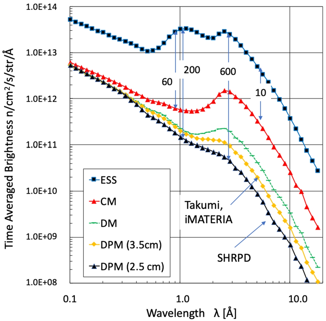
Time-averaged brightness of ESS (5 MW) moderators, which are advanced coupled moderator. J-PARC (1 MW) has three types of moderators; coupled (CM), decoupled (DM), and decoupled poisoned moderators (DPM) (the last one with two distinct moderation characteristics), all of them Para-Hydrogen moderators at 20 K. The brightness here is defined as that at the surface of moderators [6]. In the figure instruments viewing each moderator are depicted.
Since the pulse time-width can be adjusted by the decoupling technique [20], there are three types of moderators at J-PARC (one of them is split into two characteristics). Those are the coupled moderator (CM), decoupled moderator (DM), and decoupled poisoned moderator (DPM, asymmetrically poisoned to provide a poisoning plate depth of 2.5 cm on one side and 3.5 cm the other). Here, we focus on the decoupled poisoned moderators which are viewed by high-resolution diffractometer, SHRPD (viewing the 2.5 cm side) and the high throughput diffractometer iMATERIA and engineering diffractometer TAKUMI (both viewing the 3.5 cm side). Figure 1 shows the time averaged brightness of J-PARC moderators at the moderator surface in comparison to that of ESS as a function of wavelength [1 Å = 0.1 nm]. As we can see in Fig. 1, the time averaged brightness of ESS significantly exceeds that of J-PARC. The available brightness of DPM at 1 Å is lower by about a factor of 200 and 600 at 3 Å. Moderator design at short pulse sources is strongly coupled with instrument design. Therefore, requirements from instrumental resolution sometimes results in significantly sacrificing brightness as we will explain in more detail in the next section. Conversely, moderator performance, particularly its time structure, has a less strong connection to instrument design at a long pulse source, in which a PSC can produce an optimized time-width. As far as the time averaged brightness is concerned, it is obvious that the potential performance of ESS could far exceed that of J-PARC. However, as we will discuss in the following sections, we need to estimate “practical” brightness, which is operationally defined according to the required resolution of each instrument, and we will see the very large difference in the time averaged brightness become modest when comparing the practical brightness for a set of particular use cases, while seeing great benefits for ESS instruments in another aspect.
The resolution of TOF diffractometers is described as [3];
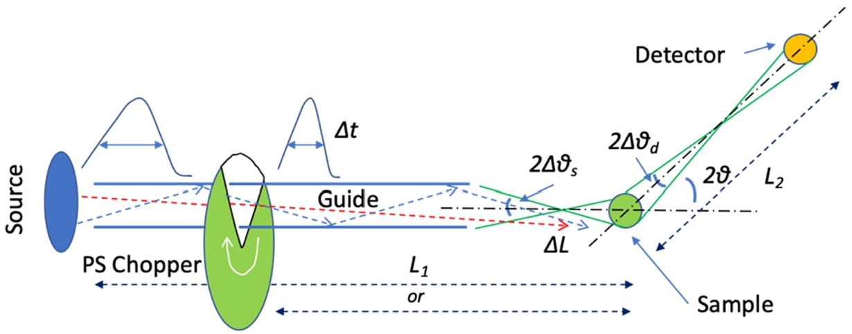
Illustration of a typical diffractometer. Neutron starts from the source on the left, propagates through a guide, is scattered at the sample to a scattering angle at
Traditionally at a short-pulsed source, powder diffractometers use a limited detector extent with a constant angular resolution with
On the other hand, at long-pulse sources, fast counter-rotating pair of choppers can produce symmetric short pulse, down to a wavelength of ∼0.5 Å and with a pulse time as low as ∼10 μs. The mechanically generated short pulses offer new perspectives for high-resolution backscattering particularly with a fully coupled cold source at ESS.

Pulse time-width as a function of wavelength [Å]. Plots are for three J-PARC’s moderators,
Figure 3 shows the pulse-peak time-width
An alternative pulse shaping technique to a fixed-time window chopper opening, is the blind chopper setup, which provides a pulse train with

Blind chopper concept. A pair of choppers create a virtual source, which behaves as a sharp pulse source with
Peak brightness of a pulsed neutron source is a helpful indicator of the expected performance of a neutron diffractometer because it directly contributes to a Bragg peak intensity. Figure 5 shows the peak brightness per second in wavelength for various J-PARC moderators and ESS. The peak brightness can also be shown on a per pulse basis, as is done in Fig. 4 and 5 of Ref. [4]. However, since an actual measurement accumulates statistics by measuring over many pulses, the presentation in Fig. 5 is more practical to foresee the diffraction signal within a given measurement time. It can be approximated by the time averaged brightness in Fig. 1 divided by the time-width in Fig. 3 for the J-PARC moderators or divided by 2.857 ms for ESS moderator, and the peak brightness per pulse can be obtained by further dividing by the source frequency of 14 Hz for ESS and 25 Hz for J-PARC. In Fig. 5 we see how the J-PARC moderators have high peak brightness even with their much lower power of the accelerator compared to ESS. Enhancing the peak brightness is a key objective in the design of short pulse sources, especially below 1 Å in the epithermal region, which significantly exceeds that of ESS.

In order to clearly see how the brightness is reflected in the diffraction peak intensity, we developed an analytical formula for the diffraction pattern as in the Appendix. According to the Appendix, the diffraction pattern is described as;
In order to clearly show the effect in the diffraction peak shape on a choice of a pulse shaping time-width
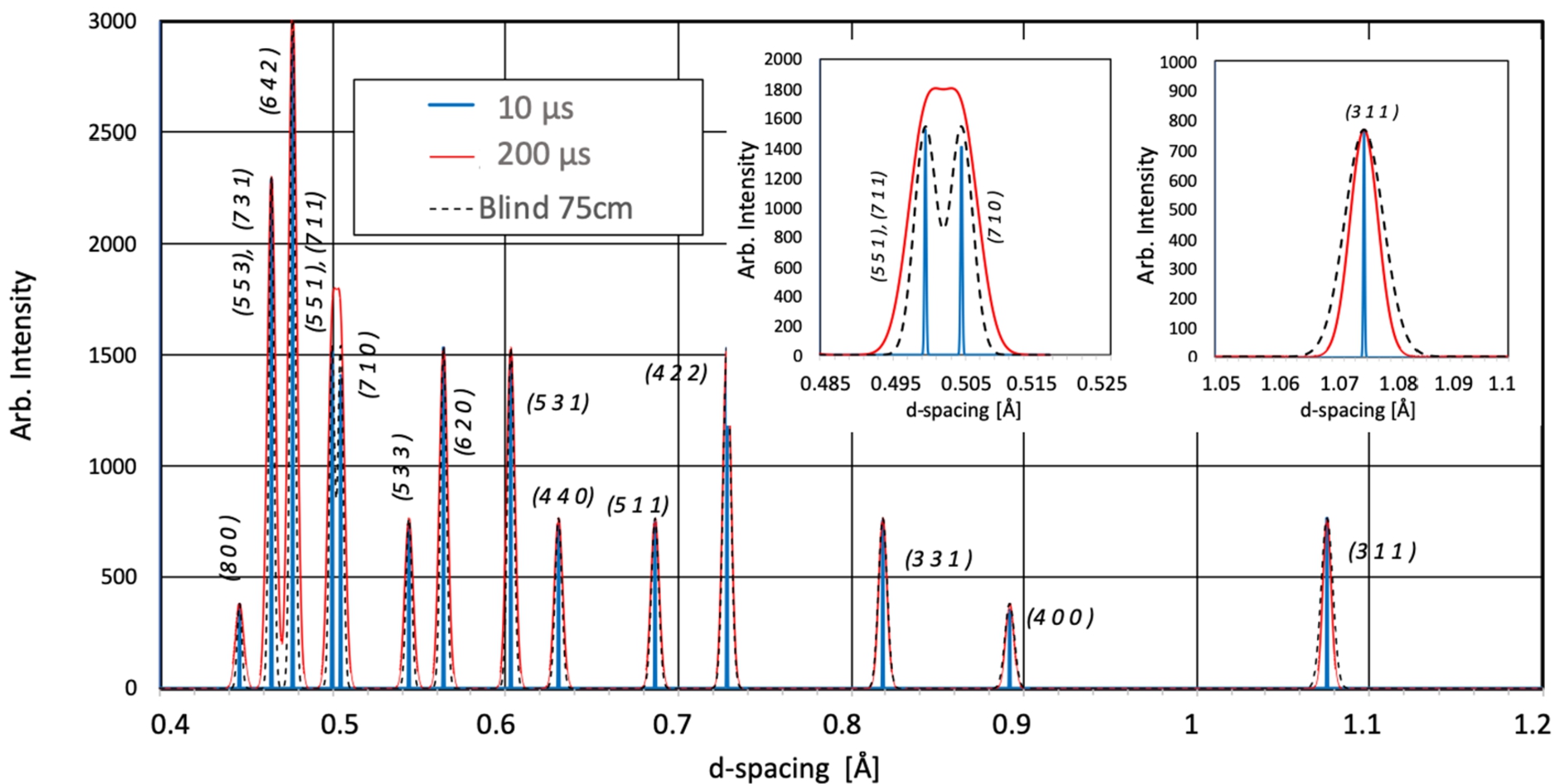
Diffraction pattern of Diamond at near backscattering at a flight distance at 70 m estimated from Eq. (6) for
Figure 6 shows Bragg reflections of diamond at a near backward scattering angle at a flight distance of 70 m, corresponding to that of DREAM, calculated by Eq. (6). Figure 6 shows three cases with
As we see in Fig. 6, the peak intensity does not change on changing the time-width, as expected from Eq. (6).
An angular component defined as
Note that in terms of actually observable intensity, the peak shape is a convolution of two peak functions

Intuitive illustration of a contribution to the flux, which is the shaded volume area,
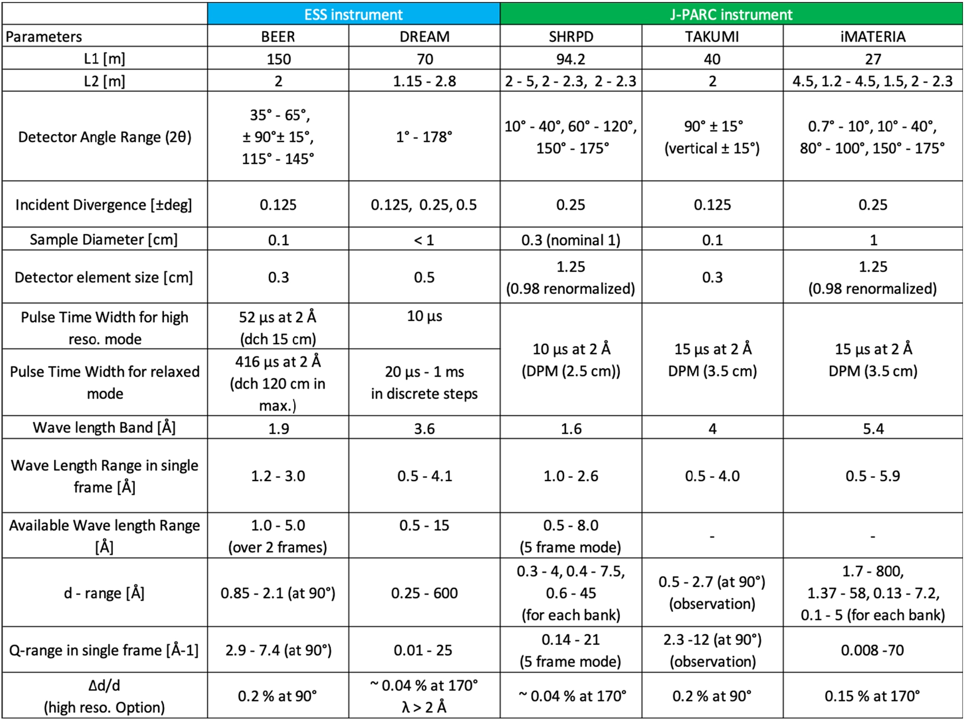
Here in a general fashion, we compare the performance of two diffractometers under construction at ESS with their counterpart operational instruments at J-PARC. Those are BEER [1, 15] and DREAM [1, 16] at ESS, and TAKUMI [7], iMATERIA [10] and SHRPD [17] at J-PARC. The relevant instrumental parameters of these diffractometers are summarized in Table 1.
Table 1 reports, the primary flight path length “
Key parameters of diffractometers. BEER, DREAM, SHRPD, TAKUMI and iMATERIA. BEER, SHRPD, iMATERIA have several detector banks, while DREAM has continuous detector coverage. The secondary flight path
and the d-range are specified for each bank. Since for BEER and the J-PARC instruments, the time-width continuously varies with the wavelength, only the time-width at 2 Å is specified in the table. BEER uses a blind chopper pair and DREAM uses fixed-time window opening. The distance
between the pair of blind choppers is given for BEER. The Q-range specifies the overall range covered by all detector banks. The element size of the helium tube detectors of SHRPD and iMATERIA is renormalized by taking the geometrical average. All the d-ranges and Q-ranges specified, except for TAKUMI, are the theoretical values estimated from the detector angles and wavelength range for single frame measurement, except for the 5-frame mode of SHRPD. The
at the specified angle is the benchmark parameter to be discussed in the text
Key parameters of diffractometers. BEER, DREAM, SHRPD, TAKUMI and iMATERIA. BEER, SHRPD, iMATERIA have several detector banks, while DREAM has continuous detector coverage. The secondary flight path
The practical Q-range does not significantly differ between the ESS and J-PARC counterpart pairs. In this regard, the two sources seem to provide a similar Q-range for conventional diffraction measurement. The exception is iMATERIA, which has a small-angle detector bank for SANS and intentionally uses epithermal neutrons by having a short
In this analysis, we compare the performance in the high-resolution option as listed in Table 1 between the two diffractometers SHRPD (
Both DREAM and SHRPD aim to provide high-resolution powder diffraction capabilities in particular at near-backscattering angles. The highest scattering angle is 178° and 175° respectively for each instrument, where a resolution higher than

Layout of DREAM [16] and SHRPD [17], showing the difference in the design concept. DREAM extracts both cold and thermal neutrons by bi-spectral switcher, stacked multi-mirrors, in the monolith beam port followed by a pin hole at 6 m. The guide system has an elliptical shape, along a straight guide axis. Pulse shaping chopper (PSC), band definition choppers (BD), high energy neutron suppression chopper (T0) tailor the time structure of neutron pulse. Detector system has a continuous coverage from small to high angle. On the other hand, SHRPD equips a curved guide with the curvature radius of
Figure 8 illustrates the conceptual design of DREAM and SHRPD, which clearly shows the difference in the design concept. DREAM extracts both cold and thermal neutrons by a bi-spectral switcher in the monolith beam port by taking a great advantage of ESS moderator, which has a very high brightness at both the cold and thermal region. A pulse shaping chopper (PSC) is set at 6 m right outside the monolith shield and
On the other hand, SHRPD does not have optical components in the monolith beam port in order to reduce the angular divergence of the incident beam at sample. The curved guide section starts at 8 m just outside the monolith shield (7 m) with a curvature radius of 9 km to eliminate high energy neutrons, and switches to a straight guide section at 40 m at the point at which direct line-of-sight to the source is lost. Three band-definition choppers control the bandwidth and frames. The detector system is composed of three separated banks from low angle, medium angle to high angle. In order to achieve the highest resolution, SHRPD reduces the sample size to 3 mm from the nominal size of 1 cm, which is otherwise chosen to match the detector diameter of 1.25 cm (renormalized size is 0.98 cm using the geometrical average of the helium tube detector width).
In order to realize the high resolution, SHRPD views a decoupled poisoned moderator with a Cd plate installed at 2.5 cm in depth in the moderator. It significantly sacrifices brightness as shown in Fig. 1 in comparison with the CM, but it achieves an extremely sharp pulse width [17]. On the other-hand the high-resolution option of DREAM uses a pulse shaping chopper (PSC) with a fixed-time window opening of

To show this arrangement more clearly, the time resolution is illustrated as a function of the wavelength in Fig. 9 for the wavelength band (WB) of running in single-frame mode (1-FM), with the exception of SHRPD, which mostly uses a five-frame mode (5-FM) by suppressing 4 out of 5 neutron pulses. DREAM has
We have shown the time averaged brightness in Fig. 1 and the peak brightness in Fig. 5. However, as we discussed in Section 2.4, a good metric for the measured height of the diffraction peaks for a given angular factor of

Practical brightness,
On the other hand, the flux at sample is described as
As shown in Fig. 10, the expected practical brightness of DREAM is about 5 times higher than that of SHRPD in 5-FM. However, 1-FM gives SHRPD almost comparable brightness to DREAM. Therefore, if a measurement focuses only on an important wavelength band between 1 Å and 2.6 Å, the two instruments perform comparably in high-resolution mode. Another ESS diffractometer, HEIMDAL [1] to be installed at 160 m source distance has a shorter and comparable wavelength band width of 1.7 Å to SHRPD, and can thus have twice the flux at sample of DREAM for a given resolution.
For the high-resolution mode, DREAM utilizes only
DREAM is unique to existing diffractometers at short pulse spallation sources with its flexibility in choosing time resolution via mechanical choppers. Emphasis is given to the high-resolution option, which outperforms SHRPD for wavelengths larger than 2 Å. A medium resolution setting (∼100 μs) seems particularly favourable, simultaneously matching needs for PDF, standard crystallography and high resolution at high (10–25 Å−1), medium (2–12 Å−1) and low Q (<3 Å−1), respectively. The detector covers seamlessly the entire scattering angle without a particular constraint. The data assembled into a single histogram benefit from symmetric peak shapes. However, in order to best exploit the variation of angular resolution, a new 2-D Rietveld refinement method [11] has been proposed and tested [12].
BEER [1, 15] and Takumi [7] are engineering diffractometers, and are illustrated in Fig. 11. Those instruments are aimed at a similar resolution of
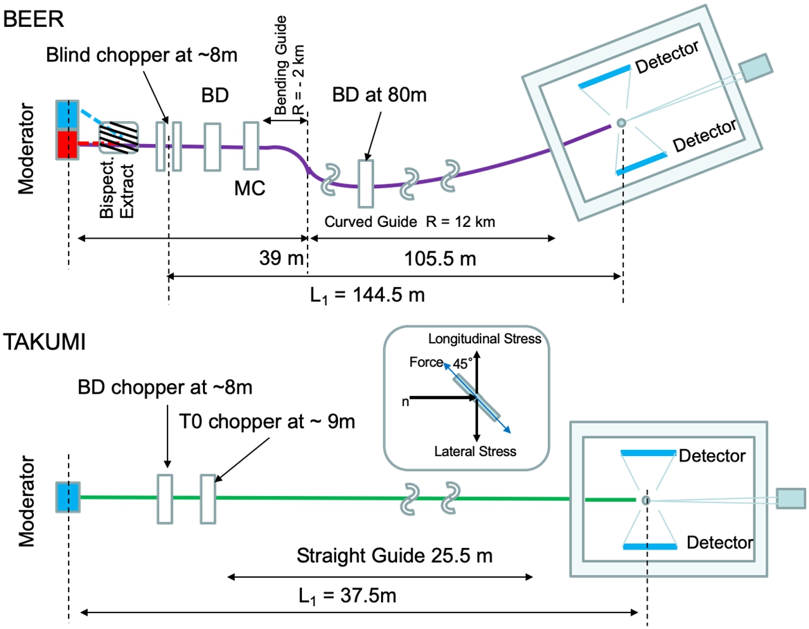
Layout of BEER [15] and TAKUMI [7], showing the difference in the design concept. BEER extracts bi-spectral beam by a multi-mirror in the monolith. Several sets of blind choppers can select different separations. There are also band definition choppers (BD) and a multiple repetition chopper (MC). The guide system has double curved sections to reject high energy neutrons as well as epithermal neutrons. The main detector system is set at ±90°. On the other hand, TAKUMI has a straight guide to accept epithermal neutrons. High energy neutrons are eliminated by a T0 background suppression chopper. Currently detector banks are deployed only at ±90° to analyze lateral and longitudinal stress simultaneously. The inset also shows how the stress along lateral and longitudinal direction can be observed by applying a loading force along 45° to the incident beam.
The actual chopper opening time of BEER is, however, much wider than the corresponding pulse time-width of TAKUMI because of the much longer flight path of 150 m; they are 15 μs for TAKUMI and 52 μs for BEER at 2 Å, as shown in Table 1. Thanks to the slower repetition rate of 14 Hz at ESS, a sufficiently wide wavelength band from 1 Å to 3 Å is maintained, as shown in Fig. 9. As a consequence, the available brightness at the sample position of BEER, is much higher than TAKUMI as is observed in Fig. 10, although the brightness of BEER drops down in the short wavelength range below about 1 Å and into the epithermal region.
Another benefit from the long ESS pulse is pulse multiplication as planned for BEER by pulse modulation [1]. This technique creates many pulses from the long pulse and is used to observe a specific Bragg peak diffraction, which is well separated in time-of-flight from other indexed Bragg peaks, and is especially effective to improve statistics for a time-resolved in-situ measurement of Engineering materials.
Therefore, in general, it can be said that the design of BEER is well adapted and optimized to the source characteristics of ESS with its long pulse and low repetition rate. Although the brightness of BEER is higher than that of TAKUMI in the conventional wavelength range, Takumi can utilize neutrons up to the epithermal region. In the analysis we found that the time resolution of both instruments seems to be far better than the required performance for stress analysis unless performing high-resolution diffraction at back scattering. The time resolution is about 25% of the angular resolution at 90°. BEER can, however, mitigate this mismatch of the time resolution by adjusting the distance,
The long pulse source ESS will give great opportunities to tailor neutron pulses with pulse shaping chopper systems by trading brightness (equivalently flux) versus time resolution. In addition, there is the benefit of a symmetric clean pulse shape, giving reliable structure refinement analysis. We did not illustrate this effect here. However, it is clearly advantageous compared to the asymmetric pulse shape obtained at short-pulse sources, created by the moderation process [19]. The slower repetition rate of 14 Hz at ESS also favours long instruments by taking a longer pulse shaping time-width while keeping a sufficiently wide wavelength band. As a consequence, ESS’s diffractometers benefit from an enhancement in the practical brightness as shown in Fig. 10 and their practical performance is significantly better than what would be expected simply from inspection of the peak brightness, shown in Fig. 5.
The flexible performance of ESS instruments due to the tunability of the chopper opening time-width is summarized in Table 1;
While a short-pulse spallation source does not offer the flexibility of mechanical pulse tuning, the optimization of the moderators is crucial for specific instruments. In this analysis, we have found that the peak time-width at J-PARC seems to be much narrower than required especially for TAKUMI, and it could be a good idea to retune the poisoning depth of the decoupled poisoned moderator on the occasion of its replacement in the future. Since those instruments have been already applied for a lot of various experiments, the practical experiences will give a very good guide for the improvement of the moderator system.
The comparisons shown here were done under the assumption of the perfect brilliance transfer of the guide system to see an intrinsic merit/demerit attributed to the difference of the source character. However, in reality a long guide is more sensitive to cumulative misalignments and other optical imperfections. The long ESS instruments may thus be more likely to experience loss of some performance from these effects. The degradation of transfer depends strongly on the engineering design of the guide system and details of the beam extraction system from the moderator. We expect that Fig. 10 gives a good intuitive representation of the expected performance comparison, but ultimately only operational experience at ESS will determine the true comparison.
Also, in this analysis we did not assess the detector layout, detector efficiency, background etc. But the realistic performance of instruments strongly depends on those factors but not only on the source performance. Here, we remark the point, which is out of scope of this report.
Conclusion
We have provided an overview of five planned and existing diffractometers at ESS and J-PARC. There is a perception today that a sharp neutron source pulse structure is needed for diffraction measurements, which drives the intrinsic choice of decoupled and poisoned moderators at short-pulse sources. However, as we have seen in this analysis, that is not always the case, and by adopting an appropriate pulse shaping chopper system, instruments at long pulse source perform very well, and with an unprecedented tunability. This unique character will give a great benefit for diffractometers at ESS by balancing resolution and brightness to optimize the instrument configuration. On the other hand, it is clear that the instruments at J-PARC perform well compared to those at ESS despite the much lower source power. In addition to this, instruments at short-pulse source can naturally utilize epithermal neutrons, which provides a unique opportunity for PDF analysis at high momentum transfer and also gives less recoiling effect for light elements [3], as well as better application to highly absorbing material and very thick engineering substances. The two types of sources thus provide very distinctive and complementary roles. The real test of the instruments at a long pulse source will be evaluated with actual scientific experiments and discovering how to take best advantage of the tunable capabilities of ESS diffractometers for scientific discovery, once the facility is up and running.
Footnotes
Appendix
Here, we describe a formula specifying intensity to be observed at a detector based on Eq. (10) of Ref. [8].
For long pulse source, a choice of pulse shaping time-width is independent from other resolution components such as the angular resolution. Equation (A.1) can conveniently be described by two components. One is attributed to pulse shaping time-width and another to other resolution components, mainly the angular component.
Here, we neglect the
Therefore, Eq. (A.1) can be described by components of time and wavelength.
Figure A.1 illustrates the situation in the time-of-flight diagram to show the effects of the two terms in Eq. (A.4).
Therefore, the peak shape function in Eq. (10) of Ref. [8] is described by two functions by using the peak brightness per second;
As we described above, a choice of pulse shaping time-width is independent from other resolution components. For a simplicity, the two peak shape function,
Therefore,
And conversion from wavelength domain “λ” to time-of-flight domain “t” is made by Eq. (3).