
Abstract
The paper presents a complicated case of coalescence of yield zones between two internal cracks out of four collinear straight cracks weakened an infinite isotropic plate. Two solutions are presented for the case of opening and closing of multiple cracks under general yielding conditions. Using these two solutions and the principle of superposition, we found the analytical expressions for load-bearing capacity of the plate using complex variable method. A numerical study has been carried out to investigate the behavior of yield zone length concerning remotely applied stresses at the boundary of the plate and the impact of two outer cracks on the propagation of inner cracks due to coalesced yield zones. Results obtained are reported graphically.
Nomenclature
Constants
Young’s modulus
Elliptic integral of first, second, third kind respectively
Crack lengths
Polynomial of degree n
Actual crack tips
Tips of yield zones
Stresses acting along the rims of yield zones
Components of displacement
Complex variable
Developed plastic/yield zones
Complex potential functions
Poisson’s ratio
Shear modulus
Components of stresses
Load applied at the infinite boundary of the plate
Yield stress of the plate
Introduction
Development or existence of cracks in a structure generally catastrophic in nature. These cracks may appear in a structure because of manufacturing defects or the application of repeated load applied at the boundary of the plate. Wang et al. [20] studied that the residual strength of an aircraft fuselage has been significantly reduced due to the presence of multi-side damage. Macroscopic fatigue strength of steel was evaluated by Yokobori [22] and studied fracture mechanics for low-stress brittle fracture of steels [23]. It is quite helpful to determine the residual strength for the safety of structures that contains crack(s), also, opening of these cracks due to applied stresses. Dugdale [9] gave a model to determine the residual strength of an infinite plate weakened by a single crack. This model was further studied and extended for the case of equal and/or unequal multiple straight cracks in plenty of research works i.e. [4,7,8,11,12,16,18,21,25] etc. for various loading conditions.
A good number of analytical and/or numerical solutions for multiple crack problems with separated yield zones are available in the literature, in which authors considered various geometrical configurations of cracks and mechanical loading conditions. However, the cases of coalescence of yield zones developed between closely situated cracks were not discussed adequately. Nishimura [17] discussed the coalescence conditions of plastic zones in case of multiple cracks. Feng [10] suggested two reasons for the coalescence yield zones, the unstable crack propagation and the linking of damage localization bands. Again, Nishimura [19] investigated the conditions when adjacent plastic zones just coalesced. Stress intensity factors and crack opening displacements were calculated for multiple cracks in the studies by Bhargava and Hasan [1,2]. The case of coalesced yield zones between two cracks in piezoelectric material is discussed by Bhargava et al. [3,14]. The weight function approach is used to evaluate the stress intensity factor for multiple cracks with coalesced yield zones by Zhang et al. [5]. Stress intensity factors at the tip of the crack were obtained [24] using the method of continuous distribution of infinitesimal dislocations.
Especially the case of multiple cracks with coalesced yield zones was not discussed too much in literature. Although, this is an important phenomenon that occurs just before the formation of a macro crack after coalescence of micro cracks. Therefore, this paper is an effort to enrich the literature related to coalesced yield zones and to discuss the bearing capacity of the plate in presence of these zones. The primary motivation for the present study was to determine the effect of coalesced yield zones on the load-bearing capacity of an infinite plate containing multiple cracks. The problem taken in this paper may be considered the case that happened just before the formation of three collinear straight cracks. Closed-form analytic expressions are obtained for calculating the length of developed mechanical yield zones using the complex variable method. Numerical results are obtained for yield zone length, load-bearing capacity under general yielding conditions.
Basic equations
For two-dimensional in-plane problem, the components of stresses 𝜎
xx
, 𝜎
yy
, 𝜎
xy
, and displacements u, v, may be expressed in terms of two complex potential functions 𝛷(z), 𝛺(z) as given in [13]
In a rectangular Cartesian coordinate system oxy, consider an infinite elastic perfectly plastic plate weakened by n quasi-static straight cracks L
i
(i = 1,2, …, n) are lying on the real axis. Upper and lower edges of these cracks are subjected to the uniform stress distribution
The general solution of the Eqs (4) and (5) be written as
C
0 is determined using the loading condition at infinite boundary of the plate and remaining constants C
i
(i = 1,2, …, n) are determined using single-valuedness condition of displacements,
Stress intensity factor in mode-I type deformation at each crack tip z = z
1 is obtained by using the formula given in [8],
An ideal elastic perfectly plastic plate is considered for this analysis. The plate is weakened by four collinear straight cracks L i , i = 1,2,3,4 which is yielding at a constant uniaxial tensile stress 𝜎 ye . Cracks are open in mode-I type deformation when uniform tensile stress 𝜎 ∞ applied at the boundary of an infinite plate in a direction perpendicular to the rims of the cracks, as shown in Fig. 1, as an outcomes yield zones developed ahead of each crack tip. It is assumed that the plate will deform elastically under the application of external stresses. The yield zones between two inner cracks get coalesced on increasing load at the boundary of the plate. These yield zones together with coalesced yield zones are denoted by 𝛤 i , i = 1,2, …,7. It is assumed that the yield stress distribution 𝜎 ye is acted on the rims of yield zones to stop further opening of the cracks.

Configuration of the problem.
The solution of the problem, shown in the configuration above, is derived by superposing linear elastic solutions of two auxiliary problems. One is related to the problem of the opening of cracks when the boundary of the infinite plate is subjected to uniform stress distribution, denoted by Auxiliary problem-A. The other one is concerned with the effect of yield stresses acting on the rims of yield zones, termed as Auxiliary problem-B.
Auxiliary problem-A and its solution
Consider an infinite isotropic elastic perfectly plastic plate containing three collinear straight cracks, as shown in Fig. 2. The plate is subjected to uniform mechanical loads 𝜎
∞
at infinity, while, both upper and lower crack faces are supposed to be stress-free. Yield zones are developed ahead of each crack tip, therefore, cracks together with developed yield zone are denoted by R
1, R
2 and R
3 and are termed as extended cracks. In this case, boundary conditions of the problem are
The desired complex potential function is obtained using the methodology given in Section 2 and boundary conditions given in Eqs (14) and (15)

Configuration of the Auxiliary problem-A{}.
Solution of Auxiliary problem-A can also be taken from [15] or [11].

Configuration of the Auxiliary problem-B{}.
Consider an infinite isotropic plate weakened by four collinear straight cracks, L
1, L
2, L
3 and L
4, with coalesced yield zones, 𝛤4, between inner cracks, as shown in Fig. 3. The boundary of the plate is free from any force, while faces of the yield zones, 𝛤
i
, (i = 1,2, …,7), are subjected to uniform stress distribution, 𝜎
ye
. The cracks together with the yield zones are known as the extended cracks, denoted by R
1, R
2, R
3. The boundary conditions of the problem are
Especially in the case in which yield zones are subjected to stress distribution, 𝜎
ye
, the desired complex potential 𝛷
yield
(z) is
The integral in Eq. (19) is calculated using the fact
By virtue of the symmetric loading condition, the constants C
1 and C
3 become zero. The constant C
0 is also zero since no stress is applied at the infinite boundary of the plate. The remaining constant C
2 is determined by using the condition of single-valuedness of displacement (12). Hence,
Stress intensity factors in case of mode-I type deformation at each crack tip z
1 = a, b, c are obtained by using the formula given in [8]. The total stress intensity factors must vanish if the stresses are finite at each crack tip,
Thus, using Dugdale’s hypothesis that the stresses remain finite at each crack tip, non-linear equations are obtained in terms of applied load ratio
Similarly, the analytical expression for load ratio at the crack tip z
1 = b is calculated using Eqs (16), (19) and (21) and expressed as
Also, general expression related to the load ratio at crack tip z
1 = c is calculated using Eqs (16), (19) and (21) by taking z
1 = c
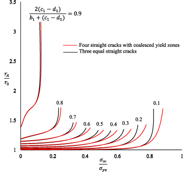
It is almost impossible to write the Eqs (22), (23) and (24) analytically for yield zone length as a function of applied load ratio. Therefore, a numerical study is carried out to discuss the length of yield zones against the increasing value of the applied load ratio. The results obtained are reported graphically. Since the case of three straight cracks is the limiting case of the cracks configuration considered in this paper, therefore, a comparative has been shown to analyze the effect of applied load ratio on yield zone lengths r A = |a − a 1|, r B = |b 1 − b| and r C = |c − c 1| at crack tips z 1 = a, b, c respectively for crack lengths L 1 = 2L 2 = 2L 3 = L 4. The results of these yield zones are normalized with the results of a single isolated Dugdale crack of the same length.
Yield zone ratio

Yield zone ratio

Yield zone ratio
Yield zone ratio
Results at the outer crack tip z = a
1 are presented in Fig. 4, which shows the variation between applied load ratio
As observed from the Fig. 4 that the yield zone length r
A
increases as the load applied the infinite boundary increases. A sharp increase in r
A
is seen when cracks are located close to each other even
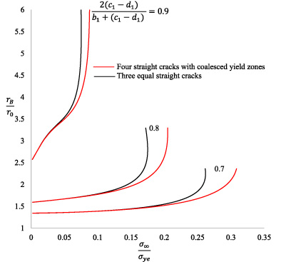
Some typical outcomes for study of four straight cracks with coalesced yield zones are presented in Fig. 6, which shows the variation between applied
Yield zone ratio
Yield zone ratio
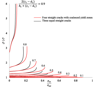
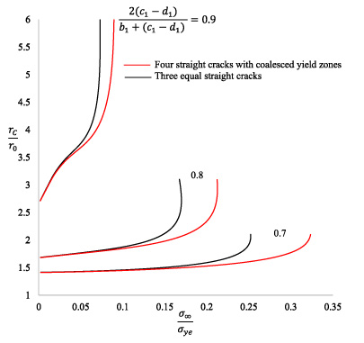
Due to coalesced yield zone at crack tip d
1 the yield zone at the crack tip c
1 is highly sensitive towards the load bearing capacity of the plate. Figure 8 provides an estimate of the yield zone length at the crack tip c
1 for different inter crack distances when the load applied at the boundary increases. At the crack tip c
1 yield zone length r
C
is normalized by
Further, for small value of
The problem discussed in the paper is the case of multiple collinear straight cracks with coalesced yield zones in an infinite isotropic plate. An analytical approach, the complex variable method, is used to solve the problem and closed-form mathematical expressions were obtained for stress intensity factor and applied load ratio using Dugdale’s hypothesis. These analytical results are useful to study the behavior of load-bearing capacity of infinite plate weakened by multiple cracks with coalesced yield zones. It is seen from the numerical results that in the case under consideration the infinite plate can bear more load rather than the case of three straight cracks of similar lengths. A significant difference in the lengths of yield zone length is seen when cracks are situated in the immediate vicinity 𝜌 = 0.9.
The results show that the configuration of four straight cracks with coalesced yield zones may be considered as the case that happen just before the formation of three macroscopic straight cracks. Variation in the load carrying capacity shows that the residual strength of the plate is significantly affected in the presence of coalesced yield zones.
Footnotes
Acknowledgement
Authors are grateful to the referees and the editors for their valuable suggestions, which improved the understandability of the paper.
Conflict of interest
None to report.