Piezoelectric materials are widely used in electronic devices like sensors. In this study, a strip saturation zone model is provided for a transversely isotropic piezoelectric plate which is cut along three equal collinear impermeable cracks. The developed saturation zones are assumed to be subjected to the linearly varying electric displacement conditions. The problem is solved using Stroh formalism and the complex variable approach. Analytic closed-form expressions are obtained for fracture parameters including crack opening displacement, crack opening potential, and saturation zone length. A numerical study also presented showing the effect of linearly varying electric displacement on the saturation zone length.
Incomplete elliptic integral of first, second and third kind respectively
Li (i = 1,2,3)
Crack lengths
Pn (z)
Polynomial of degree n
Δu2 (t)
Crack opening displacement
Δu4 (t)
Crack opening potential drop
± a, ±b, ±c
Crack tips
± a1, ±b1 ± c1
Tips of saturation zones
p (t), q (t)
Applied stresses on the yield zones
z = x1 + ix2
Complex variable
𝛤′
and N2 are the values of principal stresses at infinity, 𝛼 be the angle between N1 and the ox-axis
𝛶2 (z), 𝛶4(z)
Complex stress functions
𝜅
for the plane-stress, =3 −4𝛾 for the plane-strain
𝜎ij
Components of stress
𝜎22∞
Remotely applied stress at infinite boundary of the plate
D2∞
Electric displacement at boundary of the plate
Ds
Electric displacement on electric saturation zones.
Introduction
Piezoelectric materials are extensively utilized in the modern electromechanical devices, construction of microbalance, actuators, sensors and many other devices [15]. There is a fair chance to develop a fatigue crack due to excessive use of the devices and brittle behaviour of the piezoelectric materials [18]. However, these type of materials can be damaged permanently owing to the influence of electromechanical load. Therefore, the study of the fracture problem of such materials is gaining more and more attention from researchers in the field of fracture mechanics.
Parton [13] provides an analysis of a single cracks in piezoelectric medium under mechanical stress. Pak [12] studied the stress intensity factor criterion and the energy-release rate criterion with the framework of linear elastic fracture mechanics and investigate that the electric fields will tried to slow down the crack growth. A plane crack problem at the interface of a bi-material piezoelectric was studied by Qin et al. [14]. A mode-III crack filled with a dielectric medium was studied by Zhang et al. [19]. Zhang and Tong [20] further studied an elliptical cylinder cavity using complex potential method. McMeeking [10] discussed the concept of energy release rate for Griffith crack propagation in an infinite body. Yang [21] developed the closed form solution of mode-I crack problem in piezoelectric materials for external load to open the crack. Yokobori et al. [22] discussed the interaction between crack and a slip band based on the concept of macro and micro fracture mechanics.
The analysis of two of more cracks is a very complicated procedure due their mathematical complexity. Multiple crack problem in a piezoelectric material under uniform remote loads was studied by Gao [5] and obtained the exact solutions of the problem using complex variable method. Considering the effect of permittivity of air, Hao [7] investigated the exact solution of the problem of multiple collinear cracks in piezoelectric materials. Li [8] analyzed an infinitely long piezoelectric strip of finite width containing two equal collinear cracks under different types of uniform anti-plane shear and uniform in-plane electric loading conditions. Using the Fourier transform method, basic solution of two collinear cracks in a piezoelectric material was obtained by Liang [9]. A two-dimensional mode-I strip electro-mechanical yielding model for two equal collinear cracks present in a transversely isotropic piezoelectric plate was studied by mean Stroh formalism and complex variable technique by Bhargava et al. [2] for both semi-permeable and impermeable cracks. They also studied cohesive saturation limit electric displacement [3]. Fourier series method together with integral equation method was used by Bhargava et al. [4] to solve the problem of two semi-permeable collinear cracks in a piezoelectric materials using Fourier transform method. Strip-saturation model for two cracks problem in piezoelectric media addressed by, his work is extended by Bhargava et al. [15], Singh et al. [16]. The problem of two cracks was discussed by various researchers for different loading conditions in piezoelectric materials. However, to study the effect of outer crack on inner crack and vice vera the modelling of cracks will be extended to more than two cracks under the different boundary conditions.
A strip-saturation model is suggested in the current study for a transversely isotropic piezoelectric plate that has three equal collinear cracks. An analysis has been made in the model to study the effect of linearly varying electric displacement on the growth of the three collinear straight cracks. Analytical expressions are obtained for saturation zone length, crack opening potential drop etc. A numerical study is also carried out to investigate the effect of linearly varying electric displacement on the saturation zone length.
Basic mathematical formulation
In a rectangular Cartesian coordinate system xi(i = 1,2,3) the basic mathematical equations for anisotropic piezoelectric material in terms of stress components, 𝜎ij and electric displacement components, Di(i = 1,2,3) be expressed as:
Constitutive relations
Gradient equations
Mechanical and electrical equilibrium equations where 𝜎ij is the stress tensor, Di is the electric displacement vector, 𝜑 the electric potential, 𝛾ij is the strain tensor, Ei the electric field intensity, Cijkl the elastic stiffness tensor measured at a constant electric field, ekij the piezoelectric tensor measured in possession of a spontaneous electric field, 𝜀ik the dielectric tensor, (i, j) stress direction, k direction of electric displacement, l electric field direction and i, j, k, l = 1,2,3.
In case of two-dimensional problem all the field variables constitute a relation in x1, x2 and independent of x3. Hence, the generalized displacement vector u can be written as, using [1], where f (x1 + px2) is an analytic function, p is a constant, and a a four-element column, superscript T denotes the transpose.
For arbitrary function f (x1 + px2), Eqs (1)–(3) can be satisfied by Eqs (4) if where the matrices Q, R, S are given by
The Eq. (7) has eight complex roots p𝛼 and (𝛼 = 1,2,3,4) where p𝛼 are all imaginary because of the positive definiteness of the strain energy and electric energy densities. One can obtain the values of p𝛼 after solving the following eigenvalue problem. where
The general solution of the problem discussed in Eqs (1)–(3) can be written in the form of the following equations where and 𝜙 is the generalized stress function such that
In case of two-dimensional in-plane problem, the stress components 𝜎11, 𝜎22 and 𝜎12, may be expressed in terms of two complex potential functions 𝛷(z) and 𝛹(z) as, using Muskhelishvili [11]
Consider a plate weakened by n straight cracks Li(i = 1,2, …, n) which are lying on the real axis. The upper and lower edges of these cracks are subjected to the uniform stress distribution , . The Eqs (12) and (13) may be expressed in terms of two Hilbert problems, under the assumption limx2→0x2𝛷′(x1 + ix2) = 0.
The general solution of the Eqs (14) and (15) can be written as where
Constant C0 is determined using the loading condition at the boundary of the plate and remaining constants Ci(i =1,2, …, n) are determined by using condition of single-valued displacements,
The mathematical formulation given above is taken from the work of Wang [17], Gao [6] and Muskhelishvili [11] in order to make the paper self-sufficient.
Statement of the problem
Consider an infinite transversely isotropic piezoelectric plate containing three straight collinear cracks as shown in Fig. 1. The poling direction is normal to the faces of the cracks. Assume that the cracks are lying symmetrically along the real axis and occupying the intervals (−a, −b), (−c, c) and (b, a) respectively. Saturation zones develop ahead of each crack tip due to the application of constant uniform stress and in-plane electric displacement loading at the infinite boundary of the plate. These saturation zones occupy the intervals (−a1, −a), (−b, −b1), (−c1, −c), (c, c1), (b1, b) and (a, a1) ahead the respective crack tips. To stop the further opening of the cracks these developed saturation zones are subjected to a linearly varying electric displacement value , (say Da) where t is any point on the rims of the crack and Ds is saturation-limit electric displacement.
Schematic representation of the problem.
Solution of the problem
The problem discussed in the Section-3 is solved under the following boundary conditions, where, .
Assuming the continuity of 𝜙(x1) on the entire ox1 axis and using the Eq. (10) along with the boundary condition (23) the following Hilbert problem be formulated as,
The Hilbert problem given in Eq. (27) is solved using the methodology given in Section-2 and can be written as
Further, the boundary condition (26) along with Eq. (28) yields
To solve the problem, complex function 𝛶(z) = [𝛶1(z), 𝛶2(z), 𝛶3(z), 𝛶4(z)]T is introduced in such a way that
Consequently, the solution of Eqs (28) and (30) may be expressed as where 𝛩 = [HR]−1, HR = 2ReY , Y = iAB−1.
After expressing the Eq. (29) in component form by putting the value of h (z) from Eq. (31), we get the following Hilbert problems
Eliminating the term from Eqs (32) and (33), one can obtain
Solution of the Eq. (34) is obtained using the methodology discussed in Section 2. The solution can be written as follows where
The constants C1 = 0, C3 = 0 due to the symmetry of the geometry and the applied loading conditions. Further, the constants C0, C2 are determined using the loading conditions at the infinite boundary limz→∞𝛶2(z) = 0 and single valuedness condition around cracks rims respectively. Therefore, the constants C0, C2 are
After substituting the value of constants in Eq. (35), the final expression for potential function 𝛶2(z) is where
Moreover, in case of linearly varying electric displacement acting on the saturation zones, the Eq. (33) together with the boundary condition (25) yields
Following the methodology given by Muskhelishvili [11], the solution of the Eq. (39) can be expressed as where
The integrals appeared in Eq. (40) are evaluated using the following condition and written in terms of elliptic integrals as where,
Further, the constant D0 is determine using the condition limz→∞𝛶4(z) =0 and D2 is determined using single value of displacement components where,
The desired complex potential function 𝛶4(z) can be written as where
Having solved the problem as posed, it is necessary to discuss the applications of the complex potential function given in Eq. (48). The following sections deal with the applicability of the results obtained.
Applications
In this section, analytical expressions of important fracture parameters are determined. These parameters are used to describe the ability of the materials used against the growth of the saturation zone.
Stress intensity factor
Stress intensity factors (SIF) at each crack tip a, b, c is obtained using the well known formulae,
Stress component 𝜎22(x1) is determined using Eqs (10), (30) and (35) and substitute it into Eqs (49)–(51). Hence, the mathematical expressions for SIF at crack tips a, b and c are
The electric-displacement component is obtained by taking the fourth component of the Eq. (55)
After subsisting values of 𝛶2(z) from Eq. (38) and 𝛶4(z) from Eq. (48) into Eq. (56), we get
Using the hypothesis that the electric-displacement remains finite at each tip of the cracks, we obtained three non-linear equations at cracks tips a1, b1 and c1, where,
The Eqs (58), (59) and (60) enables to investigate the saturation zone length |a1 − a|, |b − b1| and |c1 − c| at the crack tips a, b and c respectively.
Crack opening displacement
As defined by Bhargava [2] the jump displacement vector is
Taking the second component of the Eq. (61) one can write
On substituting value of 𝛶2(x1) from Eq. (38) to Eq. (62) where,
Crack opening potential drop
By taking the fourth component of Eq. (61), we get
After putting the mathematical expression of 𝛶4(x1) from Eq. (48) to equation (64), one can write the 𝛿u4(x1) at crack tip x1 = a as
Also, at the crack tip x1 = b and at the crack tip x1 = c where,
Numerical study
During the process of solving the above problems, we found that it is almost impossible to obtain the mathematical expressions of saturation zone length in terms of applied electric displacement. In view of this, a numerical study is carried out to discuss the growth of the saturation zone on the increasing value of applied stress and electric displacement. The analysis has been made for different types of piezoelectric materials given in the Table 1.
Constants for different piezoelectric materials
Unit
PZT-4
PZT-5H
PZT-7A
PZT-7
BaTiO3
c11
109 Nm−2
139
126
148
130
150
c13
109 Nm−2
74.3
53.0
74.2
83.0
66.0
c12
109 Nm−2
77.8
55.0
76.2
83.0
66.0
c33
109 Nm−2
113
117
131
119
146
c44
109 Nm−2
25.6
35.3
25.4
25.0
44
e31
Cm−2
−6.98
−6.50
−2.10
−10.3
−4.35
e33
Cm−2
13.8
23.3
9.50
14.7
17.5
e15
Cm−2
13.4
17.0
9.70
13.5
11.4
𝜀11
10−9 C(Vm)−1
6.00
15.1
8.11
17.1
9.87
𝜀33
10−9 C(Vm)−1
5.47
13.0
7.35
18.6
11.2
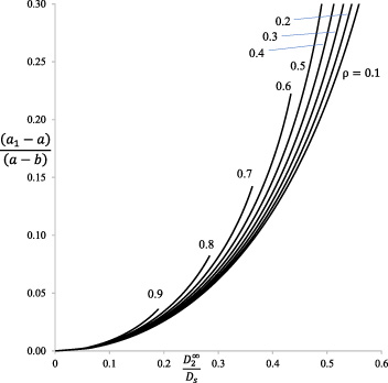
Electric load ratio versus normalized saturation zone length at tip a.
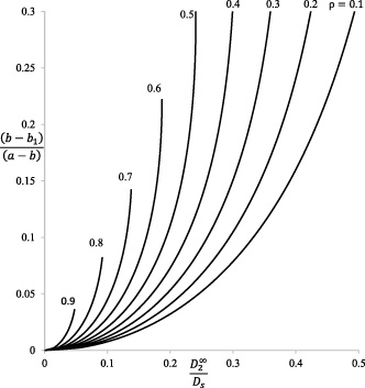
Electric load ratio versus normalized saturation zone length at tip b.
The analysis has been made to discuss the effect of the applied electric displacement ratio on the growth of saturation zones for three collinear straight cracks. Figure 2 shows the variation between electric displacement ratio, and normalized saturation zone length at the crack tip z = a using the Eq. (58). The parameter shows the inter crack distance. The higher value of 𝜌 = 0.9 demonstrates that the cracks are situated close to each other while the value 𝜌 = 0.1 shows the cracks are situated far away from each other.
It is observed from the results shown in Fig. 2 that the saturation zone length increases as applied electrical displacement to the normal saturation limit electric displacement, increases at crack tip x = a. It is observed that the saturation zone length is almost unaffected by the linear nature of electric displacement. Saturation zone length is bigger in case of closely located cracks (𝜌 = 0.9) in comparison to far away located cracks (𝜌 = 0.1).
Figure 3 shows the variation between normalized saturation zone length and electric displacement ratio at the crack tip x = b. It is observed that the zone developed at the interior tip x = b is bigger than that at the exterior tip x = a for the same applied load . And as the prescribed electric load increases the developed saturation zone size also increases at both the interior and exterior tips, as expected.
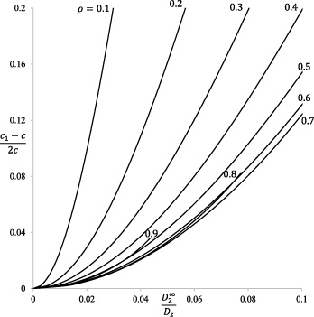
Electric load ratio versus normalized saturation zone length at tip c.
Normalized COP versus electric load ratio at tip a.
The reverse effect is seen at the crack tip x = c due to small value of for three cracks located far away from each other as shown in Fig. 4. However, for closely located cracks it shows same behavior as crack tip x = b. This means that the crack tip x = c is highly effected by the linearly varying electric displacement.
Normalized COP versus electric load ratio at tip b.
Normalized COP versus electric load ratio at tip c.
COP is calculated numerically at the crack tips x = a, b, c using Eqs (65)–(67). Figure 5 depicts the variation of COP over crack rims against the increasing value of . It is observed that COP remains negative. COP is almost same for PZT-4 and PZT-7 and less as compared to other type of materials. COP is higher for the material type PZT-7A as compared to others.
At crack tip x = b, COP is decreases faster as compared to crack tip x = a as shown in Fig. 6 at a smaller value of for different types of piezoelectric materials. Almost negligible potential drop is observed for the closely located cracks. As far COP at the crack tip x = c is concern, the tip is highly effected by the linear nature of electric displacement. A sharp decline is seen in COP at the crack tip at x = c due to very small value of electric displacement.
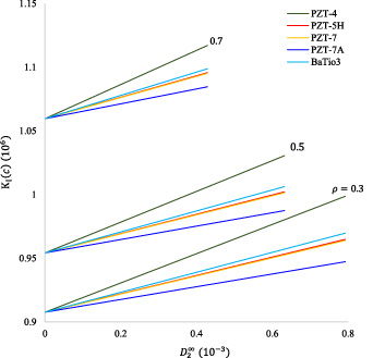
SIF given in Eqs (52)–(54) are evaluated numerically. The effect of piezoelectric properties on SIF at the crack tips x = a, x = b and x = c are plotted against the increasing value of applied electric-displacement for different piezoelectric materials. Figure 8 represents the variation between SIF at the crack tip x = a. It is seen from the results that the values of SIFs are changing by using different piezoelectric materials. It is observed as the increases the SIF increases linearly and the value is higher for PZT-4 and lower for PZT-7A and never takes zero value.
versus KI(a).
versus KI(b).
versus KI(c).
Figure 9 shows the variation between and SIF at the crack tip b. Big difference is seen between the values of SIF for 𝜌 = 0.3 and 𝜌 = 0.7 means closely located cracks shows high value of SIF at small value of . Piezoelectric material PZT-4 shows the high value of SIF in comparison to others. The effect of the applied electric field on the SIF at the crack tip c is plotted and depicted in Fig. 10. It can be seen that the SIF is higher at the cracks tip c at lesser value of applied electric field (or electric displacement) as compared to other crack tips. This shows that the middle crack is highly sensitive about applied electric field when 𝜌 = 0.7.
Conclusion
A mathematical model is proposed for piezoelectric plate which is cut along three equal collinear hairline straights cracks under linearly varying electric field. Mathematical expressions for different fracture parameters are derived in terms of elliptic integrals. Numerical study is presented for different types of piezoelectric ceramics. A comparative study is also presented for different types of piezoelectric materials.
Footnotes
Acknowledgements
The authors are grateful to the referees and the editors for their valuable suggestions, which improved the understandability of the paper.
Conflict of interest
None to report.
References
1.
BarnettD.M. and LotheJ., Dislocations and line charges in anisotropic piezoelectric insulators, Physica Status Solidi (b)67(1) (1975), 105–111. doi:10.1002/pssb.2220670108.
2.
BhargavaR.R. and JangidK., Strip electro-mechanical yielding model for piezoelectric plate cut along two equal collinear cracks, Applied Mathematical Modelling37(22) (2013), 9101–9116. doi:10.1016/j.apm.2013.04.015.
3.
BhargavaR.R. and JangidK., A mathematical strip-saturation model for a piezoelectric plane weakened by two collinear equal cracks, Mathematics and Mechanics of Solids19(6) (2014), 713–724. doi:10.1177/1081286513486285.
4.
BhargavaR.R. and VermaP.R., Strip-electro-mechanical yield model for transversely situated two semi-permeable collinear cracks in piezoelectric strip, Theoretical and Applied Fracture Mechanics81 (2016), 32–49. doi:10.1016/j.tafmec.2015.10.009.
5.
GaoC.-F. and FanW.-X., A general solution for the plane problem in piezoelectric media with collinear cracks, International Journal of Engineering Science37(3) (1999), 347–363. doi:10.1016/S0020-7225(98)00067-6.
6.
GaoC.-F.HäuslerC. and BalkeH., Periodic permeable interface cracks in piezoelectric materials, International Journal of Solids and Structures41(2) (2004), 323–335. doi:10.1016/j.ijsolstr.2003.09.044.
7.
hu HaoT., Multiple collinear cracks in a piezoelectric material, International Journal of Solids and Structures38(50) (2001), 9201–9208. doi:10.1016/S0020-7683(01)00069-5.
8.
LiX.-F., Closed-form solution for a piezoelectric strip with two collinear cracks normal to the strip boundaries, European Journal of Mechanics-A/Solids21(6) (2002), 981–989. doi:10.1016/S0997-7538(02)01241-X.
9.
LiangJ., Non-local theory solution of two collinear mode-I cracks in piezoelectric materials, Applied Mathematical Modelling32(6) (2008), 1126–1142. doi:10.1016/j.apm.2007.03.003.
10.
McMeekingR.M., The energy release rate for a griffith crack in a piezoelectric material, Engineering Fracture Mechanics71(7) (2004), 1149–1163. doi:10.1016/S0013-7944(03)00135-8.
11.
MuskhelishviliN.I., Some Basic Problems of the Mathematical Theory of Elasticity, Springer, 1963.
12.
PakY.E., Linear electro-elastic fracture mechanics of piezoelectric materials, International Journal of Fracture54(1) (1992), 54–79. doi:10.1007/BF00040857.
QinQ.-H. and YuS.-W., An arbitrarily-oriented plane crack terminating at the interface between dissimilar piezoelectric materials, International Journal of Solids and Structures34(5) (1997), 581–590. doi:10.1016/S0020-7683(96)00040-6.
15.
SinghS.SharmaK. and BhargavaR.R., Complex variable approach in studying modified polarization saturation model in two-dimensional semipermeable piezoelectric media, Applied Mathematics and Mechanics38 (2017), 1517–1532. doi:10.1007/s10483-017-2281-9.
16.
SinghS.SharmaK. and BhargavaR.R., Analytical solution for two equal collinear modified strip saturated cracks in 2-d semipermeable piezoelectric media, ZAMM-Journal of Applied Mathematics and Mechanics/ Zeitschrift für Angewandte Mathematik und Mechanik99(9) (2019), e201800244. doi:10.1002/zamm.201800244.
17.
WangT.C., Analysis of strip electric saturation model of crack problem in piezoelectric materials, International Journal of Solids and Structures37(42) (2000), 6031–6049. doi:10.1016/S0020-7683(99)00255-3.
18.
ZhangT.-Y., Fracture of piezoelectric materials, in: Encyclopedia of Thermal StressesHetnarskiR.B. (ed.), 2013, pp. 1808–1825.
19.
ZhangT.Y. and HackJ.E., Mode-III cracks in piezoelectric materials, Journal of Applied Physics71(12) (1992), 5865–5870. doi:10.1063/1.350483.
20.
ZhangT.Y. and TongP., Fracture mechanics for a mode III crack in a piezoelectric material, International Journal of Solids and Structures33(3) (1996), 343–359. doi:10.1016/0020-7683(95)00046-D.
21.
YangF., Fracture mechanics for a mode I crack in piezoelectric materials, International Journal of Solids and Structures38(21) (2001), 3813–3830. doi:10.1016/S0020-7683(00)00244-4.
22.
YokoboriT.YoshidaM.KurodaH.KameiA. and KonosuS., Non-linear interaction between main crack and near-by slip band, Engineering Fracture Mechanics7(3) (1975), 377–388. doi:10.1016/0013-7944(75)90039-9.