
Abstract
BACKGROUND:
Mono-capillary optics have been applied to increase the performance of X-ray instruments. However, performance of a mono-capillary optic strongly depends on the shape accuracy, which is determined by the diameters of the inner hollow of the capillary along the axial direction.
OBJECTIVE:
To precisely determine the inner diameter of the capillary optic used in X-ray imaging technique, which aims to replace the conventional method using a visible microscope.
METHODS:
High spatial resolution X-ray images of the mono-capillary optic were obtained by a synchrotron radiation beamline. The inner diameter of the mono-capillary optic was measured and analyzed by the pixel values of the X-ray image.
RESULT:
Edge enhancement effect was quite useful in determining the inner diameter, and the accuracy of the diameter determination was less than 1.32 μm. Many images obtained by scanning the mono-capillary optic along the axial direction were combined, and the axial profile, consisting of diameters along the axial direction, was obtained from the combined image. The X-ray imaging method could provide an accurate measurement with slope error of±19 μrad.
CONCLUSIONS:
Applying X-ray imaging technique to determine the inner diameter of a mono-capillary optic can contribute to increasing fabrication accuracy of the mono-capillary optic through a feedback process between the fabrication and measurement of its diameter.
Introduction
X-rays are very useful to inspect and measure the inner structures of an object without destruction, and they have been widely used in the field of medicine, industry, and science [1–7]. To improve the performance of an X-ray instrument or system, X-ray optics have been employed frequently [8–17]. One type of X-ray optics is mono-capillary optics [18–23], which are based on the total reflection of X-rays on an ultra-smooth [24, 25] inner surface of a capillary. Generally, mono-capillary optics are made by glass, and the critical angle of glass capillary optics is very small at roughly less than 0.2° [26], which results in a very small inner diameter depending on X-ray energy and application [27]. Conventionally, mono-capillary optics have been used in focusing X-rays, and have been employed in synchrotron radiation beamlines as well as X-ray analysis systems, X-ray diffractometers, and X-ray fluorescence analysis systems.
When focusing X-rays, the shape of the mono-capillary optics with axial symmetry is very important, because the focused X-ray spot strongly depends on their shape accuracy [28, 29]. For example, a typical design of a focusing mono-capillary optic can make a blurred spot of approximately 12 μm in diameter under a slope error of 0.1 mrad rms. A mono-capillary optic is usually fabricated from a long glass tube by a pulling system [30]. The shape of a mono-capillary optic is controlled by the change of diameter along the axial direction. The diameter of the capillary depends on the dwell time between the narrow-heated zone of the furnace in the puller and the glass tube, which is at a constant temperature around the glass melting point, as well as the tension loaded to the glass tube. The dwell time can be calculated from the intended shape of the mono-capillary optic. In the fabrication process, the inner and outer diameters of the glass tube are changed together. When the furnace finally arrives at the intended position at the design length of the mono-capillary optic, the fabrication process is completed.
In the fabrication of a mono-capillary optic, accurate diameter control is not easy, because it is difficult to measure the inner diameter precisely. Conventionally, an optical microscope has been used to measure the diameter of capillary optics [20]. However, the accuracy of such measurement is insufficient because of the depth of focus of the optical microscope and the circular shape of the capillary optic. In addition, the inner diameter of capillary optics has been indirectly estimated from the measurement of the outer diameter under the assumption that the ratio of inner to outer diameters is constant along the axis direction.
To measurement the inner diameter of a mono-capillary optic directly and precisely, X-ray imaging method was employed. The X-ray imaging of absorption contrast is a well-known technique in medicine [31–34] and nondestructive inspection [35–38]. When a sample is irradiated by X-rays, the density differences between objects inside the sample induce at difference of the number of X-ray photons recorded on an X-ray detector and produce an X-ray absorption contrast image. An X-ray imaging system could be constructed to realize the design performance, especially spatial resolution, using an X-ray source, a detector, and various other components [39]. An imaging system of a high spatial resolution at the sub-micrometer level requires a specialized X-ray source, such as an X-ray tube of ultra-small focused-spot size [40, 41] and synchrotron radiation. X-ray absorption contrast image with a high spatial resolution can be applied to observe fine structures in samples.
In this paper, we propose a new method of high-resolution X-ray imaging by using beamline of synchrotron radiation facility to measure the inner diameter of mono-capillary optics directly and precisely.
Experimental set-up
Preparation of a capillary optic
A glass capillary optic could be fabricated from a glass tube by controlling its diameter along the axial direction. A Pyrex glass tube of 4-mm outer diameter and 230-μm inner diameter was loaded in a capillary puller, which had a furnace heating up to 1,200°C, and a capillary optic of tapered shape and 60-mm length was fabricated at 680°C in approximately 5 h. The pulled part, which is the capillary optic, was cut off from the base glass tube with a diamond cutter. Figure 1 shows the fabricated glass capillary optic of tapered shape.
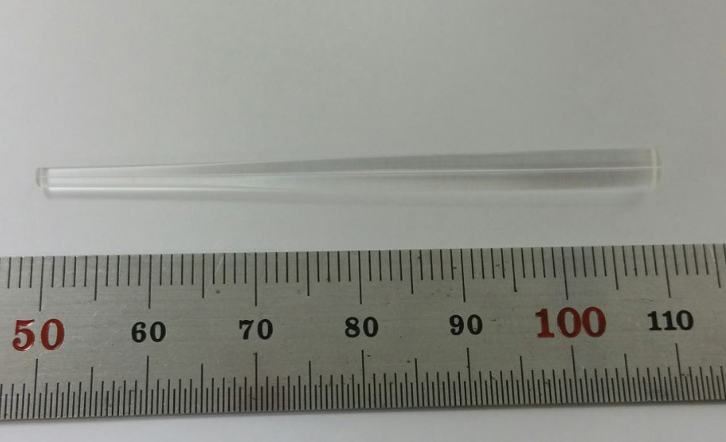
Capillary optic with a tapered shape and 60-mm length fabricated using a capillary puller system.
The X-ray imaging beamline of a synchrotron radiation facility can provide a spatial resolution of the order of tens of nanometers. Figure 2 shows a schematic diagram of the X-ray imaging system of the 6 C beamline in the Pohang synchrotron radiation facility. A parallel beam of synchrotron radiation generated from a wiggler in the top-up mode at 3.0 GeV and 320 mA had a size of 830 μm×700 μm, which could be controlled by the beam aperture. The X-ray beam energy was 23 keV, which was obtained by a Ru/C multilayer monochromator. Motorized stages of X, Y, Z, tilts, and rotation were used for aligning and scanning a sample.
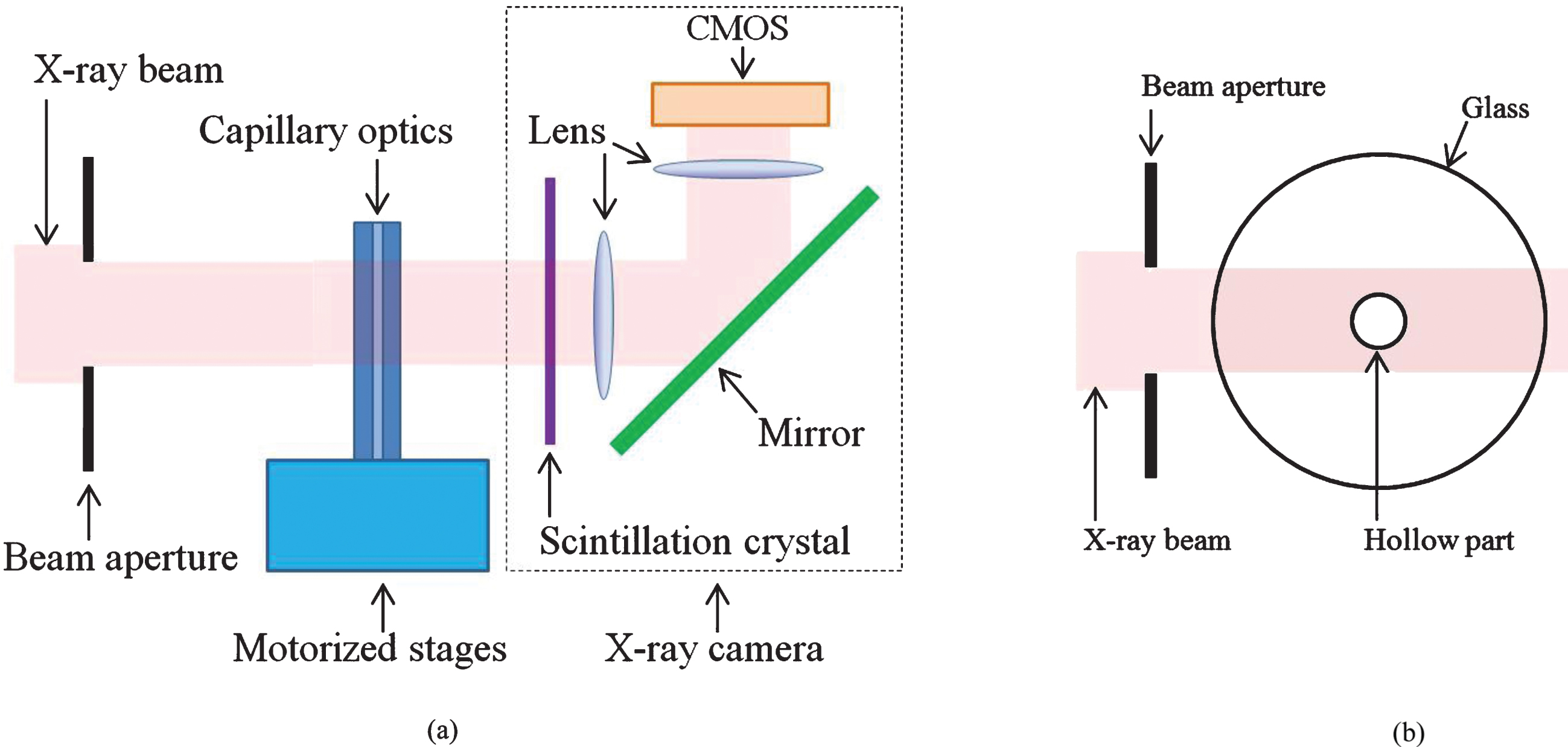
System layout (a) for obtaining X-ray image and its field of view (b). Monochromatic X-rays with an energy of 23 keV irradiates the sample, which is mounted on motorized stages, and the sample images are recorded by an X-ray camera. The imaging system has a sub-micrometer spatial resolution.
X-ray images of the capillary optic were obtained in two steps. X-rays passing through the capillary optic was first converted to visible light by a scintillation crystal of yttrium aluminum garnet doped with cerium (YAG(Ce)) with a thickness of 100 μm, following which the visible light was reflected at the tilted mirror and finally recorded on a complementary metal-oxide semiconductor (CMOS) sensor through a microscope with a 20X objective lens. The CMOS camera had a 2,560×2,160 pixel array, and the size of one pixel was 6.5 μm×6.5 μm. The achievable spatial resolution was 0.33 μm, which was verified by imaging a resolution test pattern. The distance between the center of the stages and the front of the X-ray camera was 65 mm, which was the minimum distance limited by the size of the motorized stages. The distance gave rise to the edge enhancement by phase effect and influenced the sharpness of edges in X-ray images [6, 43]. The edge enhancement effect was very useful to measure the inner diameter of the capillary optic.
The capillary optic was vertically mounted on the motorized stages by using a jig. The part with the largest diameter in the capillary optic was attached to the jig. X-ray images of the capillary optic were taken for an exposure time of 1 s. Although the field of view (830 μm×700 μm) in the beamline instrument was small, the beam intensity in the image was not uniform; therefore, the flat field correction was performed. Five white and five dark images were obtained, and each average image for the white and dark images was applied to obtain a corrected uniform image.
Because the capillary optic had a high diameter-to-length ratio and the beamline system had a very small field of view, the capillary optic was scanned along the axial direction to take images of different parts of the capillary optic. Individual images could be combined to obtain a large-scale image. The maximum scan length was 40 mm, which was limited by the stroke of the motorized stage.
Results
The inner diameter of the capillary optic was measured from the acquired X-ray image. The pixel values of the X-ray absorption image did not show large differences, because the inner diameter was very small. The difference of the number of X-ray photons (ΔN) between the glass part and hollow part in the capillary optic is
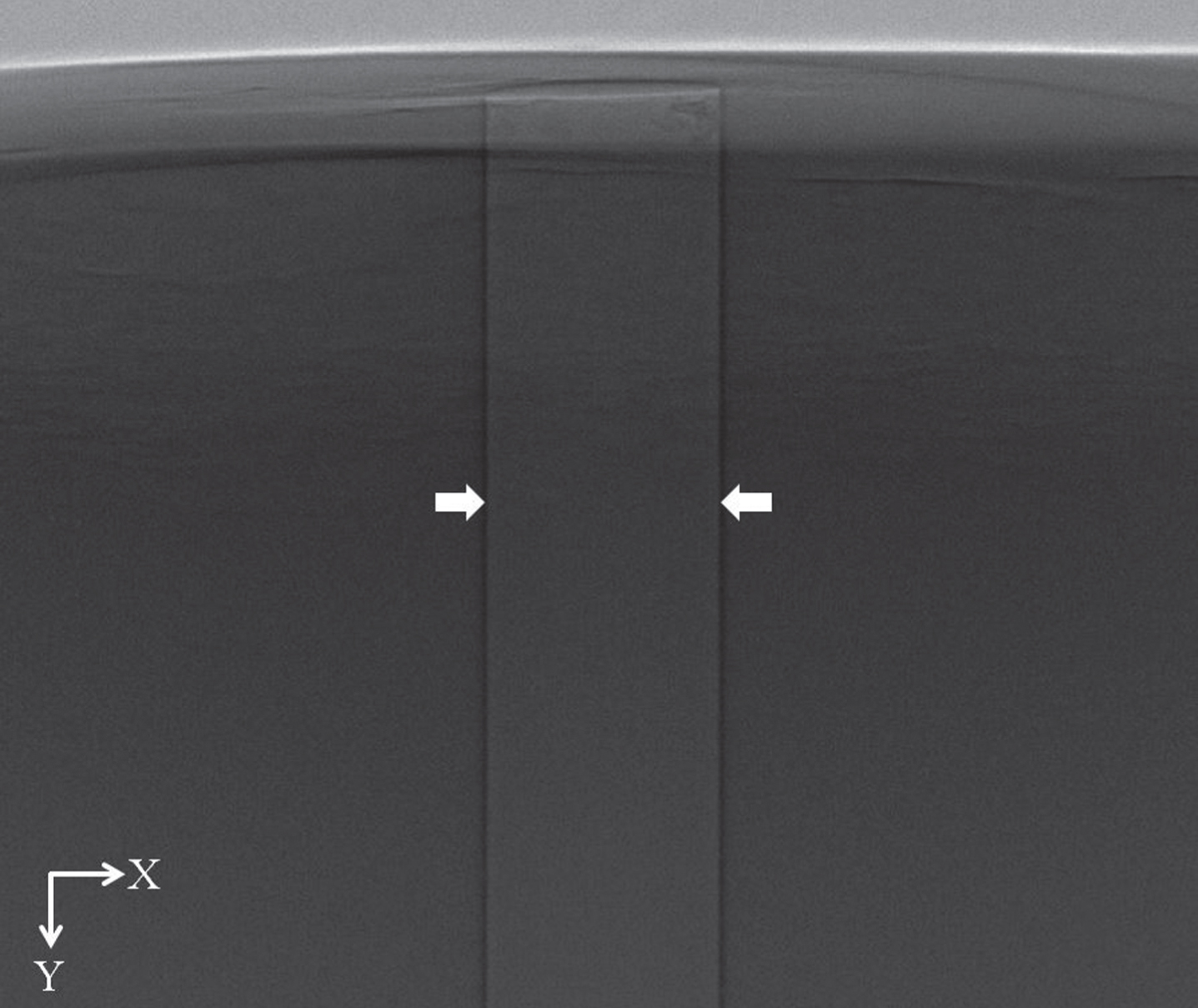
X-ray image of the end part of the capillary optic. Two boundaries, shown in white arrows, inside the hollow part of the capillary optic are observed clearly.
The boundary between glass and air hollow in the capillary optic was clearly distinguished by the edge enhancement which resulted from phase effect. The profile along the width direction (X direction) was plotted at the position of white arrows in the Fig. 3, and two dominant valleys, indicated by two black arrows, can be clearly observed in Fig. 4 (a). The two valleys were matched to two dark straight lines (boundaries) in Fig. 3. The distance between two valleys was the diameter of the capillary optic at that position. Figure 4 (b) shows an enlarged profile of the right boundary. There were two choices for determining the boundary between the glass and hollow part. One was to use the average pixel value of the glass part, which determined the boundary indicated by position A, as shown in Fig. 4 (b). Another was position B shown in Fig. 4 (b), which corresponded to half of the height difference between the valley and the first peak on the left side of the valley. Both boundary positions were almost the same, and the difference was less than 2 pixels (0.66 μm). The accuracy of determining the inner diameter is less than 4 pixels (1.32 μm) because of the two boundaries. The latter method was used to determine the boundary in this study. Using Fig. 3, the diameter of the capillary optic was measured as shown in Fig. 5. The inner diameter of the capillary optic at each Y position (or pixels in the Y direction) was almost constant at 108.33±0.67 μm.
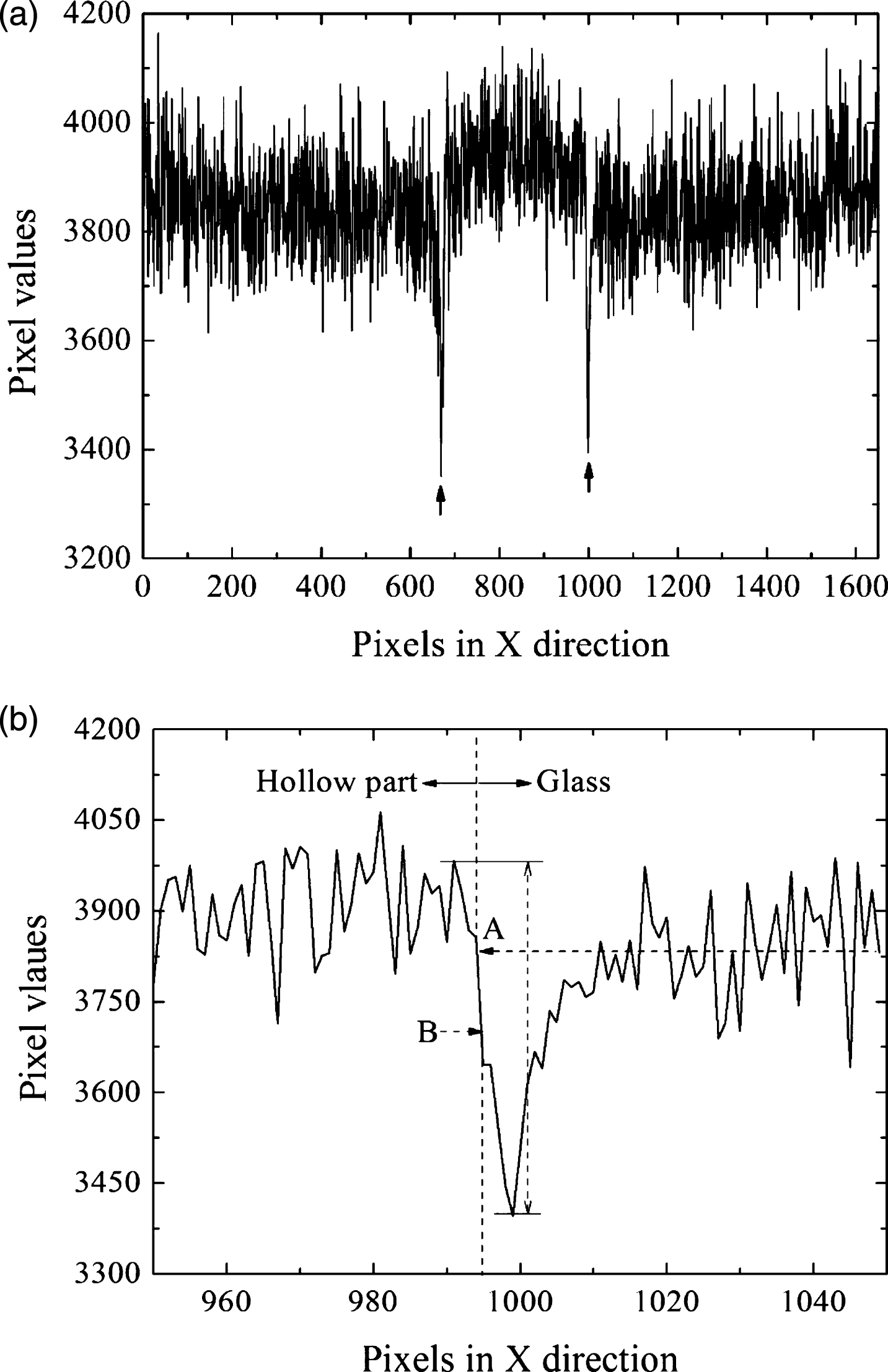
Image profile (a) and its right boundary (b) for the end part of the capillary optic. The two arrows in (a) correspond to the two boundaries of the inside hollow part of the capillary optic.
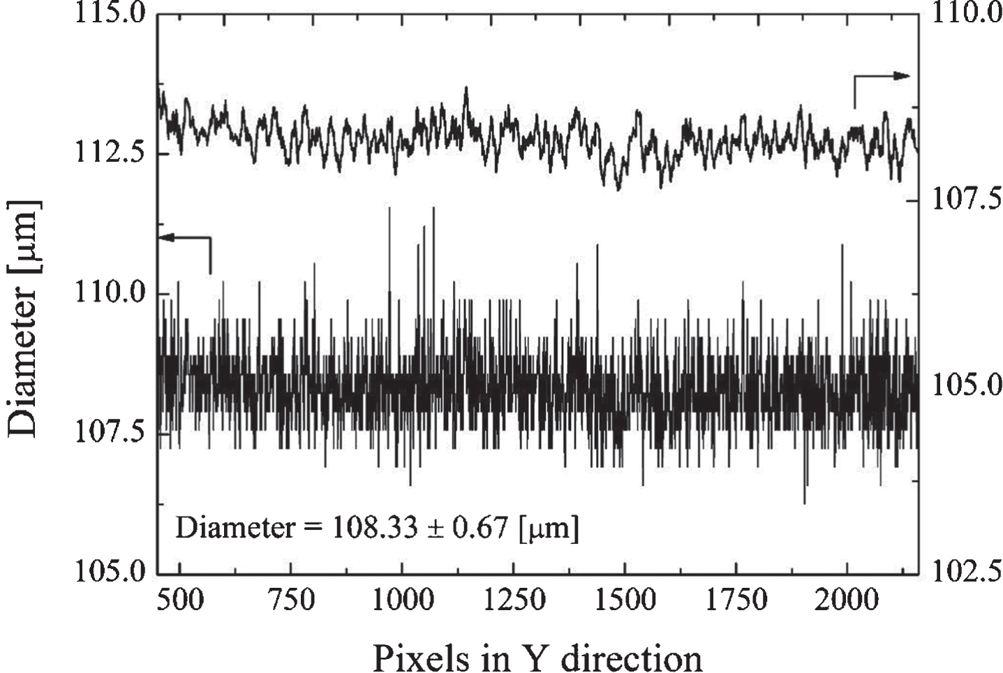
Measurement of inner diameter of the end part of the capillary optic. Pixel values in the X direction are converted to length, and the length yields the diameter of the capillary optic at the Y pixel position. The diameter of the local region is almost constant, and the local slope error was 0.7 mrad.
Slope variation of local region in the mono-capillary optic was examined by using a data smoothing method, eleven-point smoothing, for the measured raw data as shown in Fig. 5. A spatial frequency of approximately 0.05 μm-1 was dominant in high frequency and a frequency of 2.3 mm-1 in middle frequency region was also observed. A local slope error of 0.7 mrad was within the length of 700 μm for the mono-capillary optic.
The diameter along the optical axis could be obtained with the large-scale image of the capillary optic. The large-scale image of 800 μm×35 mm size was made by combining 50 images of 800 μm×700 μm size along the optical axis using image processing. Figure 6 shows the shape profile of a 35-mm long capillary optic, which was designed to have a tapered profile. However, an error of the diameter was observed, as shown in Fig. 6. The maximum deviation was 6.1 μm from the design shape, and the slope error of the mono-capillary optic was 0.35 mrad. The combined image could measure a slope error of±19 μrad under the accuracy of the diameter determination, 1.32 μm. In addition, a local slope error in the middle frequency region could also be obtained from the local diameter such as Fig. 5.
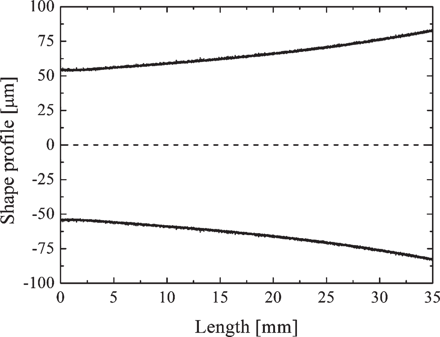
Profile of the capillary optic from its end to a length of 35 mm. The profile was obtained from the combined image of many scanned images in the Y direction.
The measurement of inner diameter of a capillary optic is very important because it is strongly connected to the specifications and performance of the optic. Currently, there are no direct methods to measure the small inner diameter for capillary optics. A visible microscope could be used to measure the inner diameter indirectly. However, the measurement accuracy with a visible microscope is not high, because of the depth of focus of a microscope lens. Recently Jian et al. [29] have measured sloped error of an ellipsoidal mono-capillary optic using a digital micrometer device. The slope error of the diameter was 11 μrad rms. This measurement also used the outer diameter of the mono-capillary optic, and the inner diameter was indirectly obtained from applying the ratio between the outer and inner diameter. However, X-ray imaging method could also measure slope error of±19 μrad accuracy directly. This method can apply to fabricate a mono-capillary optic with a designed slope error of 50 μrad and measure local slope error of middle frequency within 700 μm in length. Other option to measure the inner diameter is the use of a destructive method. The cross-section plane of the capillary optic could be imaged using a scanning electron microscope with a high magnification, and the inner diameter could be analyzed from the image [44, 45]. If the capillary optic was cut off at several parts, the inner diameter of each piece would be measurable. However, the proposed X-ray imaging technique with a high spatial resolution is a non-destructive method and is a solution to measure the inner diameter directly and precisely.
Before taking X-ray images, the capillary optic was aligned on motorized stages. The inner diameter is simply measured using the X-ray image taken without fine alignment of the capillary optic. To examine the change of diameter (or distortion) along the axis direction, the capillary optic was vertically positioned on the stage. Fine alignment of the capillary optic was performed using 3 images taken at rotation angles of 0°, 90°, and 180°. In this experiment, the alignment accuracy was less than 2 pixels in the detector. However, when misalignment existed, the vertically aligned X-ray image could be acquired through image processing using two images taken at 0° and 180°.
In the beamline imaging system using synchrotron radiation, the spatial resolution and field of view of the image had a trade-off relationship. In this sense, it was not easy to measure a large inner diameter precisely. In contrast, the measurement of a small diameter would be highly accurate. Regarding the X-ray images, a high-contrast image was not easy to acquire for smaller inner diameters because of the very small absorption difference of X-rays. Contrast agents [46, 47], which have been widely used in medicine and animal experiments, could be applied to enhance the contrast in X-ray images.
Although the beamline system would provide a high accuracy in measuring the inner diameter of a capillary optic, access to the system is very limited because of a busy beam schedule and location. An X-ray imaging system using an X-ray tube can be another approach to achieve a high accuracy. In this case, a nano- or micro-focused X-ray tube should be used to reduce the penumbra effect, and an X-ray detector with a pixel size of a few tens of micrometers should be employed. However, despite using the aforementioned X-ray tube and detector, the X-ray imaging system would be limited to a spatial resolution of roughly 1 μm.
In our experiment, X-ray projection images were acquired, and inner diameters at local points of the capillary optic were examined. By using the scanned images, the profile along the axial direction was also obtained. However, the roundness of the inner diameter could not be analyzed from the projection image. The X-ray computed tomography technique could provide roundness information for a capillary optic from reconstructed section images.
Conclusion
The inner diameter of a capillary optic was examined by an X-ray imaging technique with a high spatial resolution in a synchrotron radiation beamline. The edge enhancement effect of the capillary optic assisted the detection of the boundary between the glass and hollow part, and the method of measuring the inner diameter directly using the X-ray image provided an accuracy of 1.32 μm, which is the best result reported thus far for the measurement of the inner diameter of capillary optics. By combining many scanned images along the axis direction, the axial profile, which is the shape of the capillary optic, could also be analyzed. The combined image can measure a slop error of±19 μrad under the accuracy of the diameter determination, 1.32 μm. In summary, X-ray imaging technique with a high spatial resolution enabled the measurement of the inner diameter of glass capillary optics. The precise determination of the inner diameter will provide an opportunity to develop high-performance X-ray capillary optics through feedback for the fabrication process.
Footnotes
Acknowledgments
This work was supported by the Small and Medium Business Administration No. S2319977.