
Abstract
The design of end zones to prevent severe cracking is a key requirement toward durable prestressed girders. Traditional approaches employ large amounts of steel reinforcement to attain this requirement, which may result in steel congestion. This paper investigates a hybrid girder concept that uses Ultra-High-Performance Concrete (UHPC) and Carbon Fiber Reinforced Polymer (CFRP) bars to enhance crack control and long-term durability in the end zones of prestressed girders. The objectives of this study are to quantify the UHPC zone lengths needed to restrain end zone cracks, eliminate or reduce the required amount of steel reinforcement, and investigate its replacement with CFRP bars. A finite element modeling (FEM) approach was developed for this purpose and its fidelity was validated with experimental data. The FEM results showed that UHPC zones with lengths below or equal to half of the girder depth can significantly reduce end zone cracking. CFRP bars can be added in the UHPC zones as a conservative measure to crack control, to ensure the long-term corrosion resistance of the girders.
Keywords
Introduction
One of the main concerns in the design of a prestressed girder is the tensile stress field developed in the end zone, which can cause severe cracking (fib Model Code, 2010). Bursting cracks can develop on the concrete surface and run parallel to the prestressing steel, while spalling cracks, namely diagonal and horizontal cracks, can develop in the web region. In addition, splitting cracks arise due to the Hoyer effect, which is the tendency of the prestressing steel to regain its original diameter in the end zone (Briere et al., 2013). The tensile stress field in the end zone and associated crack formation are described schematically in Figure 1. Schematic description of end zone stresses in prestressed concrete girders per fib Model Code (2010).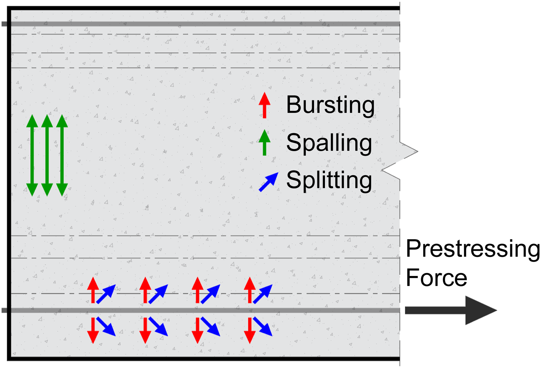
To effectively restrain crack development in the end zone, transverse steel reinforcement is used at the prestressing girder end, which is known as end zone reinforcement. As evidenced in previous studies (Crispino et al., 2009; Hamilton et al., 2013; O’Callaghan and Bayrak, 2007; 2020), the amount and location of end zone reinforcement per AASHTO LRFD Bridge Design Specifications (2020) may not adequately restrain cracking, which underlines the need for additional reinforcement, producing steel congestion. To remedy this issue, a hybrid girder concept has been recently introduced by Ronanki et al., (2019) and, later, studied further by Hamilton et al., (2020). This hybrid concept replaces the Normal Concrete (NC) of the end zone with Ultra-High-Performance Concrete (UHPC) to control end zone cracking and reduce the need for excessive amounts of reinforcement. The hybrid girder concept is shown schematically in Figure 2. The hybrid girder concept as described by Ronanki et al. (2019).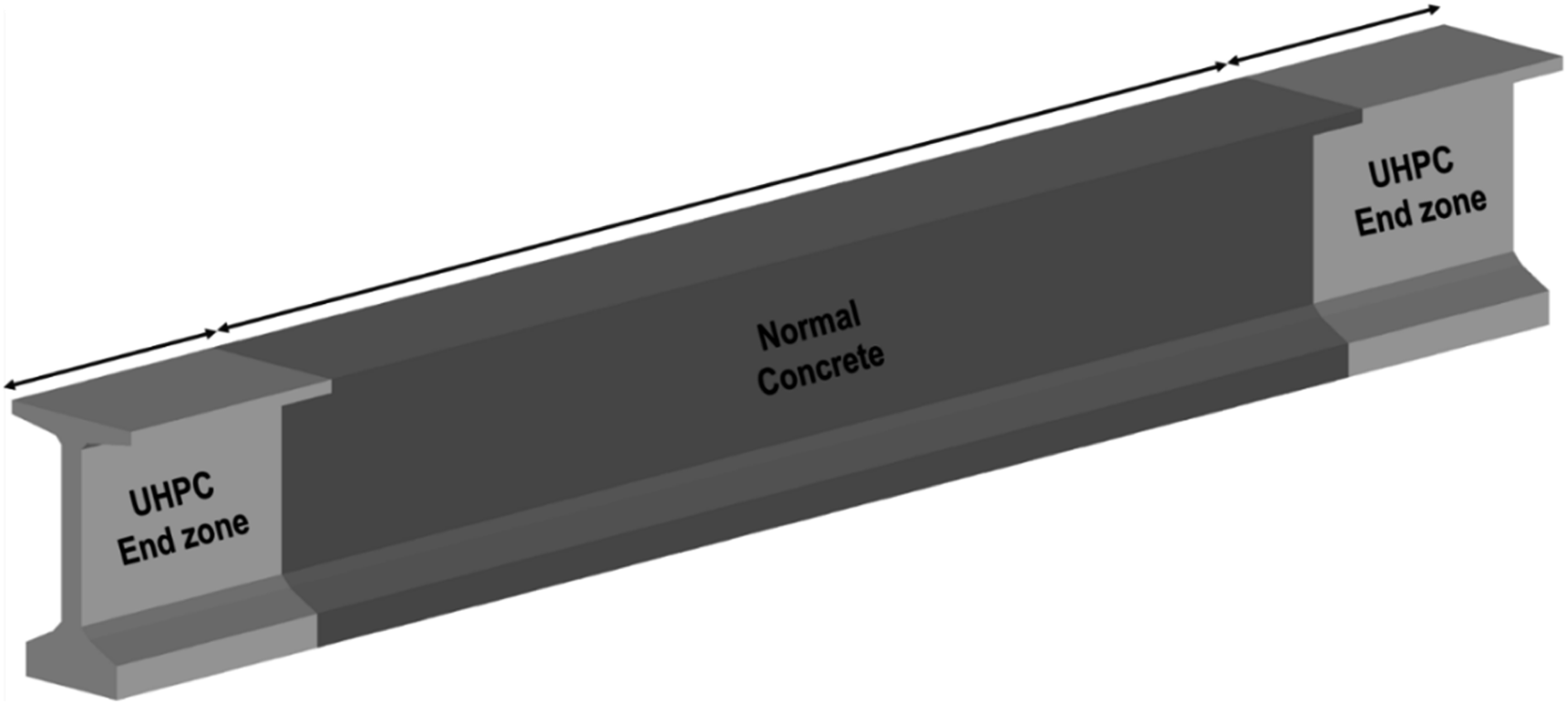
The goal of this paper is to investigate the hybrid girder concept for use in Tx girder types (O’Callaghan and Bayrak, 2007) and perform a parametric study on the UHPC zone length that is needed to minimize end zone cracking while eliminating the transverse steel reinforcement, or replacing it with corrosion-resistant Carbon Fiber Reinforced Polymer (CFRP) bars to improve the girder’s long-term durability.
Literature review
The control of end zone cracks during prestress transfer has been commonly achieved using end zone transverse reinforcement as per AASHTO and PCI guidelines. AASHTO LRFD (2020) design guidelines detail the required splitting transverse steel reinforcement (A s ) for the end zone, which is provided uniformly within h/4 (h: girder depth) from the prestressing end. The associated allowable working steel stress is f s = 135 MPa [20 ksi] as per Article 5.9.4.4.1, intended to resist a factored splitting force P r = f s A s, which is equivalent to at least 4% of the total prestress force at transfer. The same design formula is adopted in the PCI Design Handbook (2010), which, however, assumes a working stress equal to 206 MPa [30 ksi] and recommends the distribution of transverse reinforcement over a distance of h/5 from the prestressing end.
Several research studies investigated alternative approaches for detailing the end zone reinforcement. Hamilton et al., (2013) tested 14 pretensioned Florida I-Beam (FIB) girders to study the detailing of end zone reinforcement by varying the vertical and confinement reinforcement, strand quantity, and layout, in addition to including steel bearing plates and horizontal reinforcement. Furthermore, partial debonding and vertical post-tensioning were used to further mitigate end zone cracking. As part of the findings, increasing the amount of vertical end zone reinforcement by 30% compared to the control specimen led to a 10% decrease in the web crack length and a 35% reduction in the average crack width. In comparison to the control specimen, partial debonding reduced crack propagation by 29% and crack width by 43%. Crispino (2007) conducted an experimental study on a Precast Bulb-T (PCBT-53) girder and recommended a working stress of 83 MPa (12 ksi) for the end zone reinforcement, which is 40% lower than AASHTO LRFD (2020).
Several studies have also used finite element modeling (FEM) to study the behavior of the end zones during prestressing (Arab et al., 2011, 2014; Kannel et al., 1997; Mirza and Tawfik, 1978; Okumus et al., 2012; Ronanki et al., 2017, 2019; Steinberg and Semendary, 2017). Among others, Ronanki et al., (2017) investigated the effects of strand debonding and draping angle on end zone cracking, indicating that reducing the draping angle and debonding the strands can effectively control end zone cracking.
In a more recent study, Ronanki et al. (2019) introduced an alternative approach to restrain end zone cracking with the use of a hybrid girder design, where the end zone is fabricated with UHPC and the remaining girder region is fabricated with NC (Figure 2). Two girder designs were compared with FEM analyses: an NC end zone design with twenty 2-legged, ∅19 mm [#6] stirrups within a distance h from the girder end and a UHPC end zone with a length of twice the depth of the girder and eight 2-legged, ∅13 mm [#4] stirrups, which was 80% less than the reinforcement used in the NC girder. It was shown that the UHPC end zone experienced reduced tensile strains compared to the NC end zone, while the corresponding transverse bar stresses were reduced by as much as 57%. Later, Hamilton et al. (2020) studied the hybrid girder concept experimentally showing that the maximum measured crack width in UHPC end zones can be reduced to about 25% of the crack widths observed in NC end zones.
Research significance
This paper investigates the hybrid girder concept for use in Tx girder types to enhance end zone crack control and durability. The objectives of this study are to: (a) optimize the UHPC zone length for Tx girder design; (b) assess the feasibility of eliminating or reducing the transverse steel reinforcement in the end zone, to reduce steel congestion and simplify the end zone construction; and (c) examine the performance of UHPC combined with CFRP reinforcement as a viable alternative to steel reinforcement, to ensure long-term corrosion resistance of the end zone. In case (c), CFRP was selected over other types of FRP owing to its larger modulus of elasticity, which is needed for end zone crack control. Findings in this paper show that UHPC end zones as short as h/2 (h: girder depth) with a significantly reduced amount of reinforcement can restrain end zone cracking for girders designed with different prestressing demands.
Research methodology
An FEM approach was developed to investigate the design of a prestressed end zone with UHPC and replacement of transverse steel reinforcement with CFRP bars. The first step was to verify the accuracy of the FEM in simulating the UHPC constitutive behavior, the prestress transfer mechanism through bond to concrete, the stress distribution in end zone transverse reinforcement, and the associated end zone cracking. Next, the FEM approach was used to perform a parametric study with test variables being the length of the UHPC zone, the amount of transverse steel reinforcement, and its replacement by CFRP bars.
Prototype girders
Key girder design parameters.
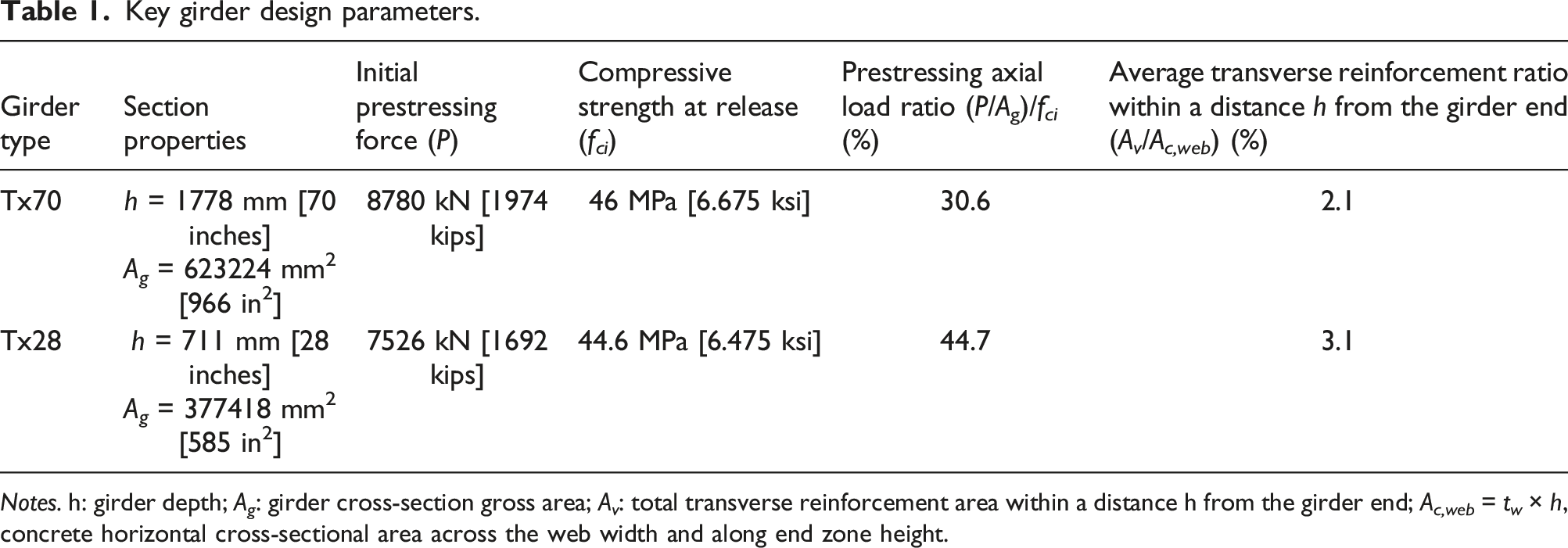
Notes. h: girder depth; A g : girder cross-section gross area; A v : total transverse reinforcement area within a distance h from the girder end; A c,web = t w × h, concrete horizontal cross-sectional area across the web width and along end zone height.
The reference design of the two girders followed AASHTO (2007) provisions to provide a steel stress resistance of not less than 4% percent of the prestressing force at transfer and an allowable working steel stress of 138 MPa [20 ksi]. In the referenced study (O’Callaghan and Bayrak, 2007), the end zone steel reinforcement was distributed over a length of h/4 from the girder end. In Figure 3, the transverse reinforcement used for end zone crack control is marked in dashed lines, while the remaining transverse reinforcing bars (solid lines) were included as part of the shear design of the two girders. End zone details of Tx70 and Tx28 pretensioned girders, as described by (O’Callaghan and Bayrak, 2007) [All dimensions in mm].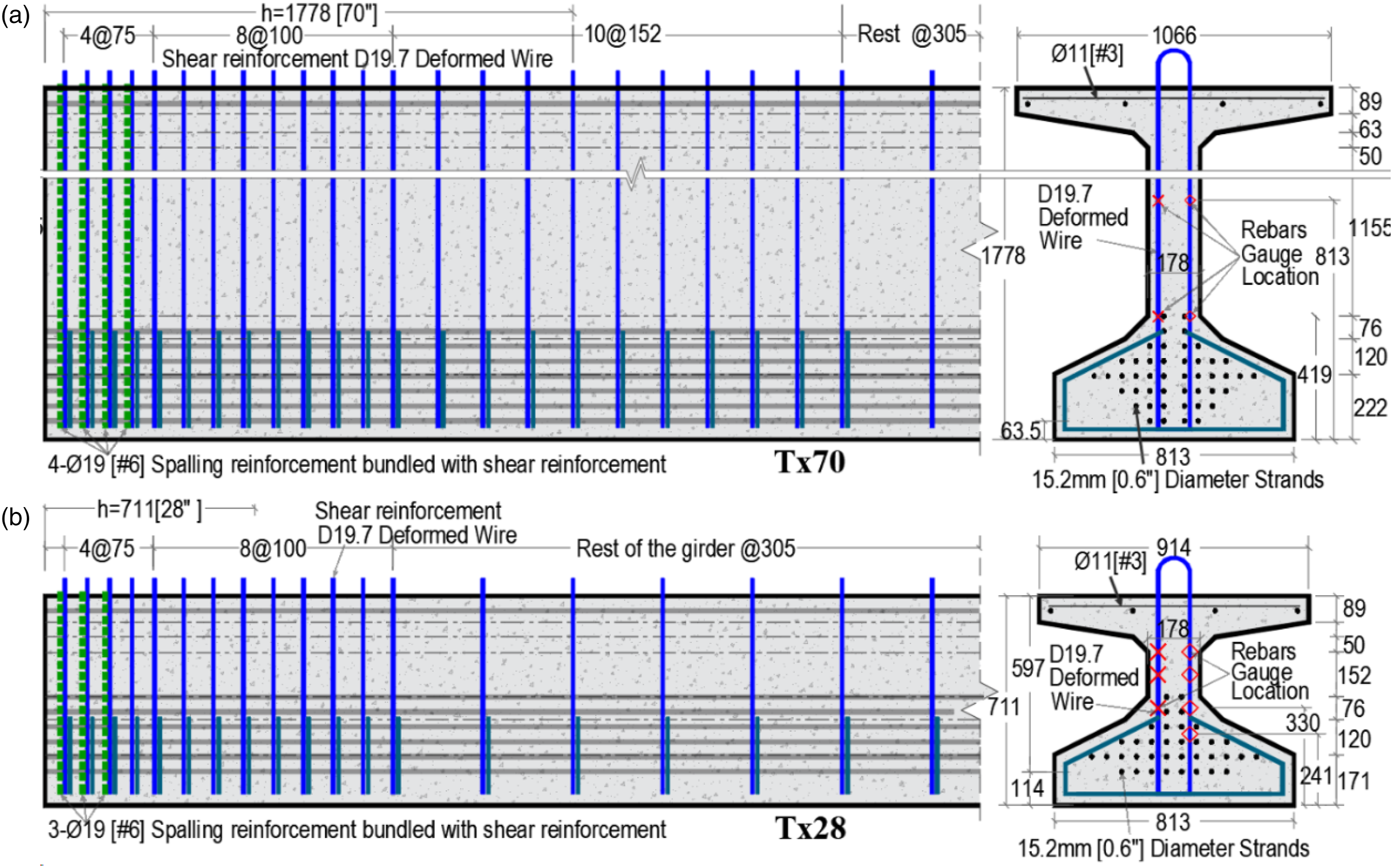
Description of finite element models
This section describes the FEM developed to study the end zone behavior of the Tx70 and Tx28 girders using the software ATENA-GiD (Červenka et al., 2021).
Problem setup
Only one-quarter of each girder was simulated to reduce the computational effort by taking advantage of the girders’ symmetry in the longitudinal and transverse directions. Each girder model included half of the 9.14 m [30 ft] span and half of the girder cross-section. Each model was subjected to appropriate boundary conditions as shown in Figure 4(a). The first region represented the girder's disturbed zone by prestressing, which spanned over a length equal to the girder depth of 1778 mm [70 inches]. This region was discretized with a finer hexahedral mesh with a characteristic element edge length of 25.4 mm [1.0 inch] and the second region was discretized with a coarser mesh with an edge length of 50 mm [2.0 inches]. The pin support condition at the girder end during detensioning was simulated by constraining the girder bottom edge in the vertical direction. Figure 4(b) shows the mesh discretization of the FE model for the Tx70 girder along with its boundary conditions. Within the scope of this study, the interfacial interaction of UHPC to NC was modeled with full bond, assuming that it does not influence the mechanism of prestress transfer. The initial prestressing force, prior to the strand release, was applied by inducing a uniform strain distribution in the strand elements as an initial condition to the finite element problem. The corresponding strain values for Tx70 and Tx28 were 0.007 and 0.008, respectively, which were based on the design prestressing forces applied to the two girders in the referenced study (O’Callaghan and Bayrak, 2007). To simulate the mechanism of prestress transfer, a bond-slip model was used to account for the interface shear transfer between the strands and the surrounding concrete, which is further explained in the next section. FEM representing a quarter of the Tx70 girder: (a) Model geometry; (b) Mesh and boundary conditions.
Constitutive models
This section describes the constitutive laws that were used for modeling the NC, UHPC, reinforcement, and bond-slip relations between reinforcement and concrete.
Normal concrete
The C3DNonLinCementitous2 model, which is a standard concrete model in ATENA (Červenka et al., 2021) was used to simulate the constitutive law of NC. The associated concrete compressive strength at transfer is specified in Table 1.
Ultra-high-performance concrete
Parameters defining the developed constitutive model of UHPC.

Note. ε pl : plastic strain; ε f : fracture strain; σ c : compressive stress; σ t : tensile stress.
The cylinder and bending prism FEMs were discretized with wedge (prism) and hexahedral finite elements (Červenka et al., 2021), respectively, using a characteristic element edge size of 25. 4 mm [1.0 inch]. Figure 5(a) and (b) compare the FEM results with the corresponding envelopes of the experimental responses, which were created based on data obtained from multiple UHPC cylinder and prism tests. Overall, it is seen that the UHPC constitutive law adequately captured the cylinder and bending prism responses. However, a discrepancy was noted in the elastic response of the bending tests. This is attributed to differences in the experimentally measured moduli of elasticity for tension and compression. For example, the constitutive law assumed a modulus of elasticity equal to 46,400 MPa [6,730 ksi] for both compression and tension, which was, however, lower than the experimental elastic modulus for tension, being estimated experimentally to be 53,900 MPa [7,817 ksi]. This explains the lower initial stiffness observed in the comparisons for the bending tests in Figure 5(b). UHPC FEMs in comparison with experimental results by Yap (2020). (a) Cylinder compressive stress-strain curve. (b) Bending prism load-deflection curve.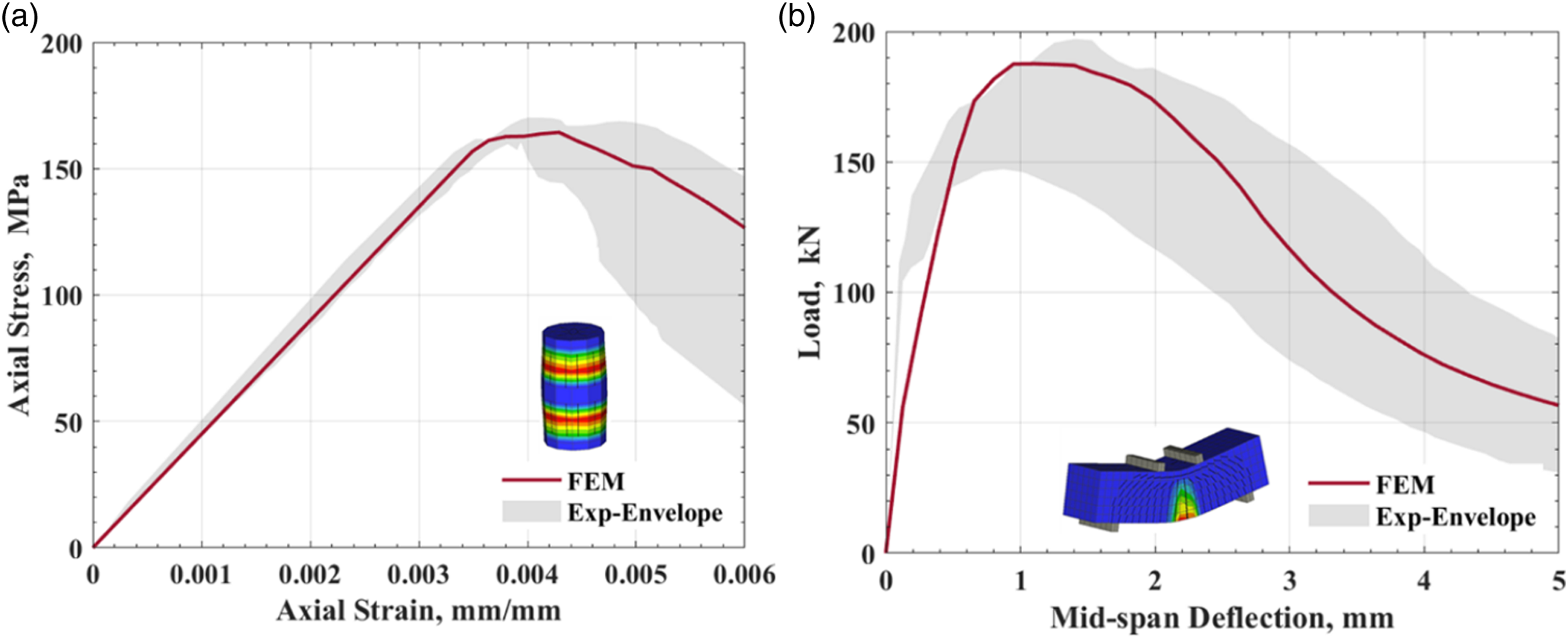
Steel reinforcement
Steel reinforcement and prestressing strands were modeled with truss elements. The constitutive law for both steel reinforcement and strands was a bi-linear curve (Červenka et al., 2021), as shown in Figure 6(a). The associated material parameters are listed in Table 3. Constitutive models: (a) Bi-linear stress-strain law for steel reinforcement (Červenka et al., 2021); (b) Stress-strain law for CFRP reinforcement in comparison with steel reinforcement. Model parameters for steel reinforcement and prestressing strands. Notes. A
b
: area of bar; f
y
: yield strength of reinforcement; f
u
: Ultimate tensile strength; E
s
: modulus of elasticity; ε
u
: ultimate strain; D19.7: welded-wire designation, where D denotes the deformed wire and 19.7 denotes a cross-sectional area of 0.197 in2.

Fiber reinforced polymer reinforcement
Model parameters for CFRP reinforcement.
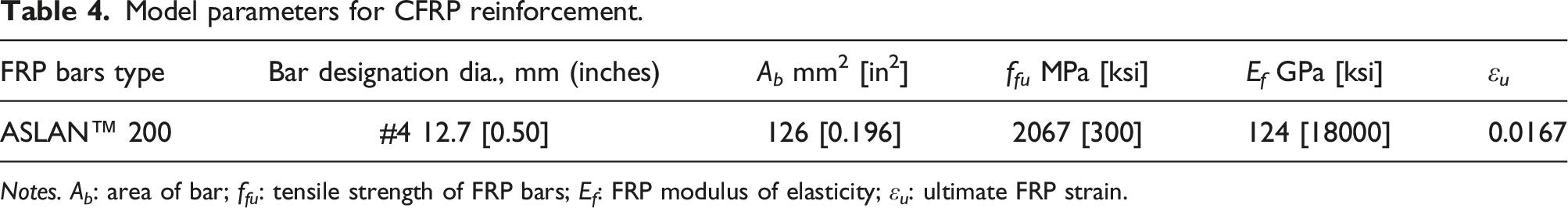
Notes. A b : area of bar; f fu : tensile strength of FRP bars; E f : FRP modulus of elasticity; ε u : ultimate FRP strain.
Bond-slip model
Parameters of bond-slip model per fib model code (2010).
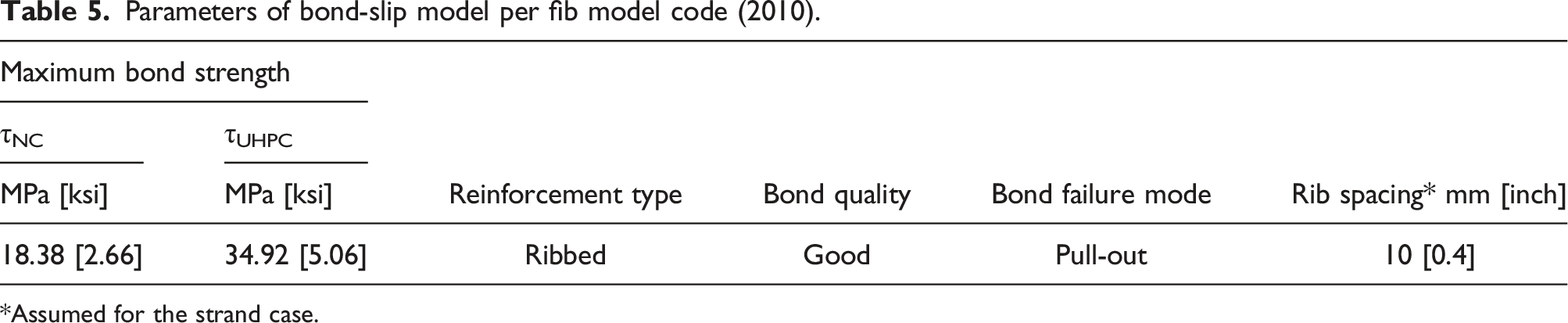
*Assumed for the strand case.
For the case of NC, the accuracy of the bond-slip law was verified with an experimental study of a prestressed mono-strand beam (Oh and Kim, 2000). The beam was modeled with hexahedral elements and a characteristic element edge size of 25.4 mm [1.0 inch], while the strands were modeled with truss elements that were prestressed at 0.75f
pu
. This prestress level was incorporated in the FEM as an initial strain condition in the strands. The model geometry and test setup are shown in Figure 7(a). The beam had one strand with a diameter of 15.2 mm [0.6 inch] and a concrete compressive strength of 61.2 MPa [8.87 ksi] at transfer. Figure 7(b) compares the experimental compressive concrete strain distribution with the FEM results. As expected, the compressive concrete strain increased from the ends of the specimen over the prestress transfer length, a behavior that was captured well by the interface bond-slip law. M12-H-C4-1 Mono-strand beam transfer length experiment by Oh and Kim (2000): (a) test set up, (b) experimental and FEM results of concrete strains along the beam, and UHPC transfer length experiment by Shin et al. (2018): (c) test setup, (d) experimental and FEM results of UHPC strains along the beams. [All dimensions in mm].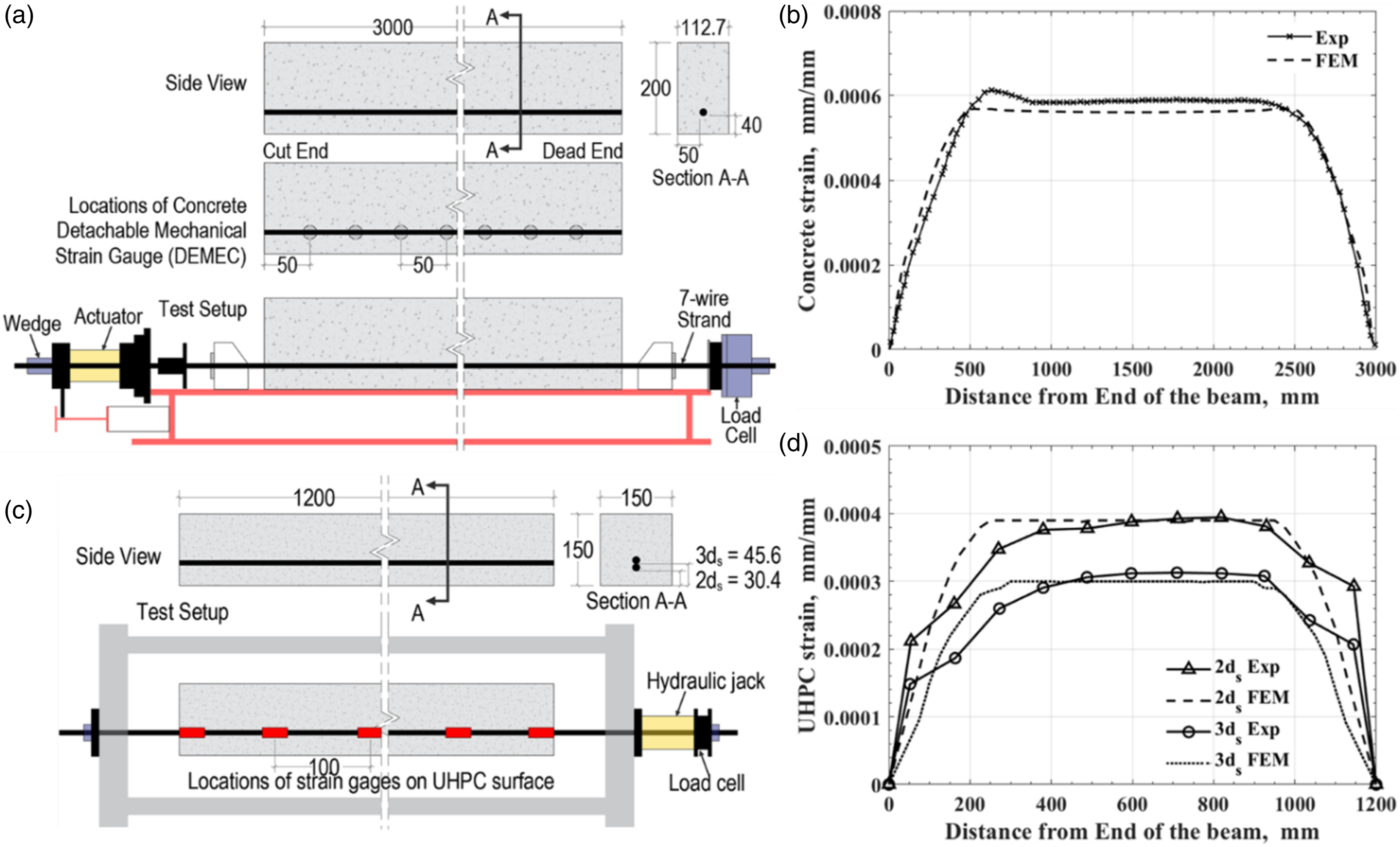
Similarly, two UHPC pretensioned beams (depicted in Figure 7(c)) tested by Shin et al. (2018) were used to investigate the accuracy of the bond-slip law for UHPC. The two beams featured single-strand reinforcement that was pretensioned to 90% of the strand yield strength (f py = 1585 MPa [230 ksi]). The UHPC mix had an average compressive strength of 183.8 MPa [26.67 ksi]. Strands with a diameter of 15.2 mm [0.6 inch] were positioned at varying concrete cover depths. The validation encompassed concrete covers equivalent to two (2d s ) and three (3d s ) times the strand diameter, where d s denotes the strand diameter. As illustrated in Figure 7(d), the experimental compressive concrete strain distribution across the UHPC beams compared well with the FEM results of both beams.
Comparison with experimental girder end zone tests
In this section, the FEM with the above-referenced constitutive relations was validated for simulating the crack profile in the end zone region and associated stress distribution in the transverse steel reinforcement, using data from Tx28 and Tx70 NC girder tests (O’Callaghan and Bayrak, 2007).
In the FEM, the crack widths, denoted as w, were calculated as w = ε
cr
L
t
, where ε
cr
is the cracking strain normal to the crack propagation and L
t
is the characteristic element length parallel to ε
cr
. Figure 8 presents the experimental crack pattern observed upon prestressing of the two girders in comparison with the FEM results. The figure shows a qualitative agreement in terms of the experimentally measured crack pattern and FEM’s crack contour. Furthermore, the FEM was able to adequately capture the range of crack width magnitudes observed in the experiments. Based on the experimental data, the maximum crack widths in Tx70 occurred at approximately 600 mm [24 inches] from the girder end, with a magnitude of 0.178 mm [0.007 inch]. The FEM computed crack width magnitudes within the same range as the experimental values and estimated the maximum crack width to occur near the same location as the experiment. However, it slightly overestimated the maximum crack width to be 0.284 mm [0.011 inch], which can be attributed to localized mesh size effects. It is noted that the spalling stresses detected at the girder face were high enough to cause web cracking, with a maximum width of 0.127 mm [0.005 inch]. In the Tx28 girder, both FEM and experiment showed the cracks to propagate along the web and bottom flange connection. The maximum crack width measured experimentally was 0.228 mm [0.009 inch] compared to 0.221 mm [0.0087 inch] that was computed in the FEM. Tx70: (a) Experimental crack profile (O’Callaghan and Bayrak, 2007) and (b) FEM results, and Tx28: (c) Experimental crack profile and (d) FEM results.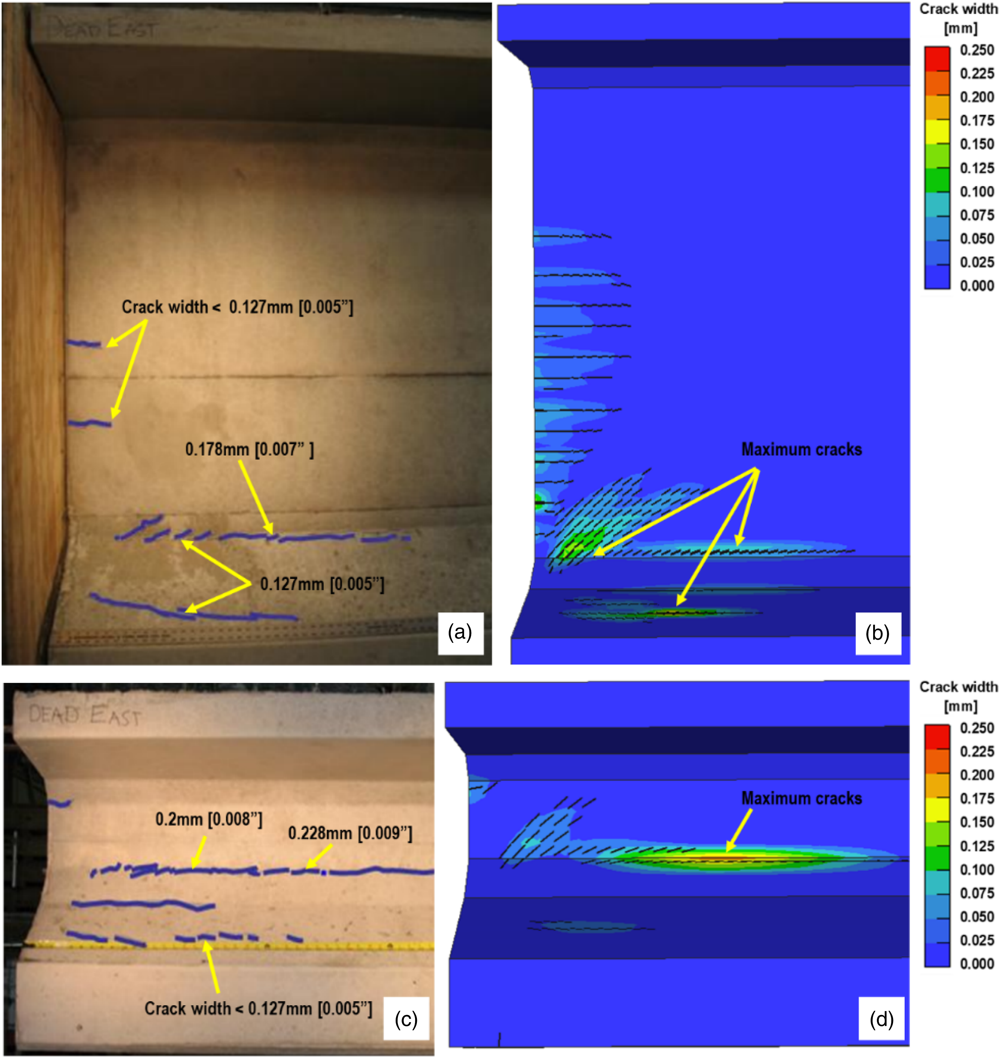
Furthermore, Figure 9 compares the experimentally measured stresses in the transverse steel reinforcement with the FEM results. In both the FEM and experiment, the maximum bar stresses in Tx70 (Figure 9(a)) occurred approximately between 300 to 900 mm [12 to 36 inches] from the prestressing end, which corresponded to a distance equal to half of the girder depth (h/2). In Tx28 (Figure 9(b)), the maximum stresses occurred between 250 to 800 mm [10 to 32 inches], or after h/4. The bursting stresses in the transverse reinforcement of Tx70 and Tx28 girders were found to exceed the allowable working stress limit for end zone reinforcement design as per AASHTO LRFD (2020). Comparison between experimental (O’Callaghan and Bayrak, 2007) and FEM results of stress distribution in the transverse steel reinforcement. (a) Tx70. (b) Tx28.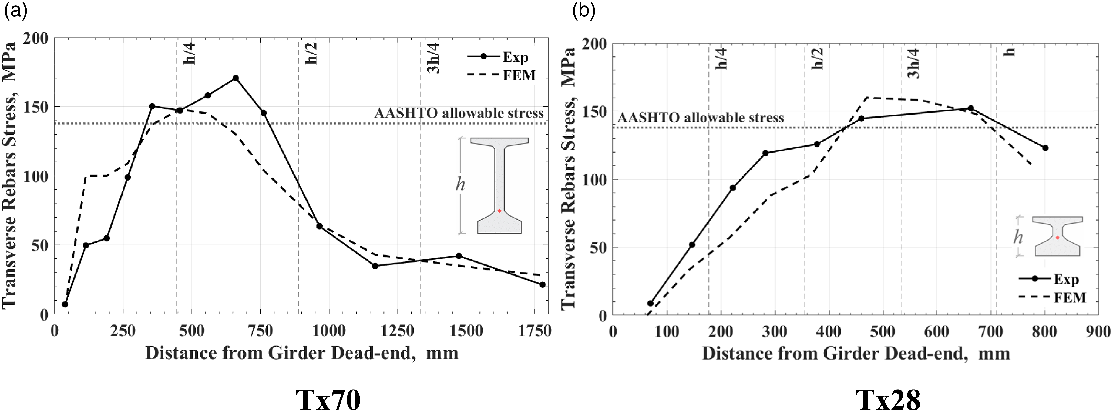
Parametric study
The results from Figure 9 in comparison with AASHTO guidelines indicate that allowable bar stresses and associated crack widths can be exceeded despite the use of large amounts of transverse reinforcement in the end zone. As discussed in Table 1, the transverse reinforcement ratios within a distance h from the girder end were 2.1% and 3.1% for Tx70 and Tx28, respectively. These observations motivated a parametric study to investigate the use of a UHPC region for the end zone of Tx girders, which was, next, combined with CFRP bars to replace the steel reinforcement. The parametric study was performed using the FEM approach detailed in the previous sections.
Ultra-high-performance concrete end zone
Test variables in this parametric study included the length of the UHPC zone, which was selected to vary from h/4 to h by an increment of h/4, and the ratio of transverse steel reinforcement within the UHPC zone. Two cases were considered in the latter variable based on the design details in Figure 3: (1) Case #1: No transverse reinforcement within the UHPC region and (2) Case #2: elimination of the end zone reinforcement from the UHPC region (i.e., reinforcement marked with dashed lines in Figure 3), but preservation of the transverse reinforcement intended for shear resistance (i.e., reinforcement marked with solid lines in Figure 3). The transverse reinforcement in the NC region was preserved in all cases.
Matrix of UHPC-enhanced girders.
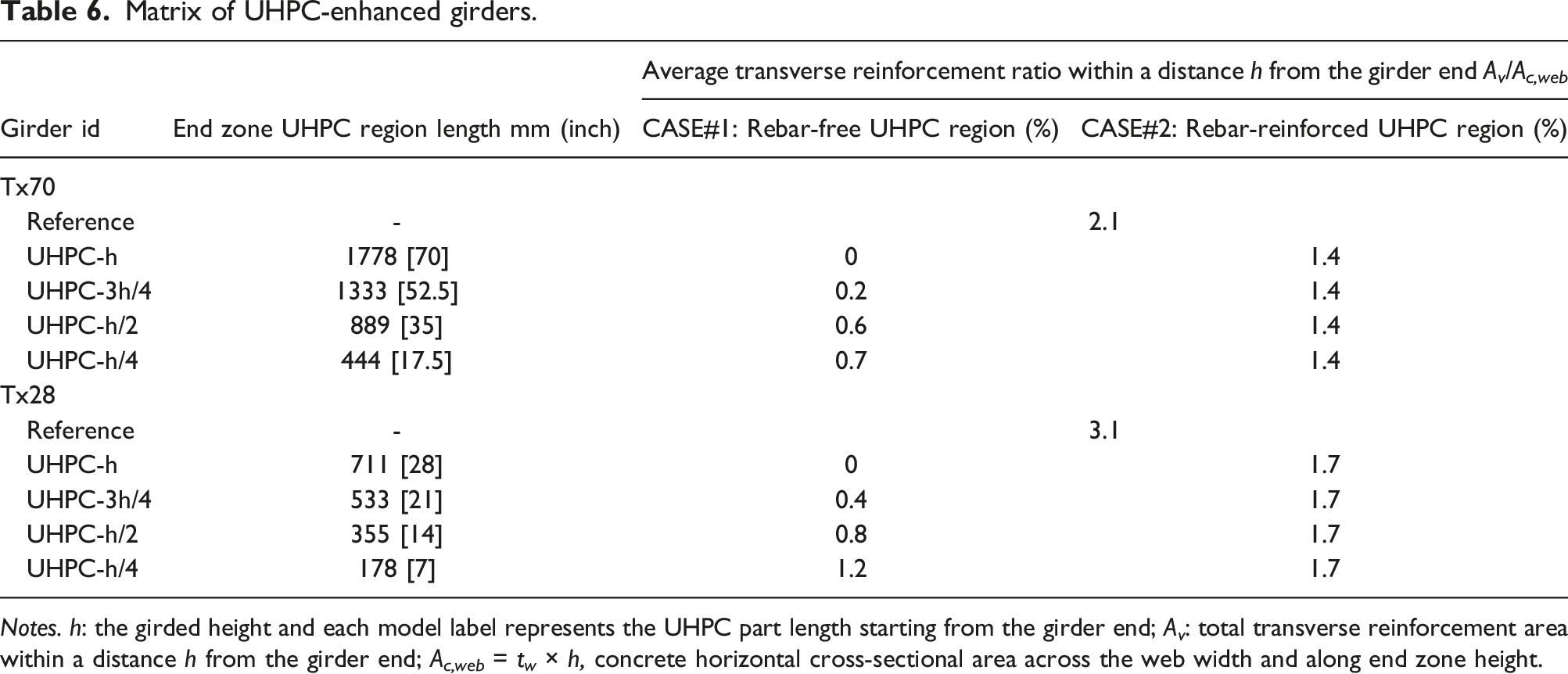
Notes. h: the girded height and each model label represents the UHPC part length starting from the girder end; A v : total transverse reinforcement area within a distance h from the girder end; A c,web = t w × h, concrete horizontal cross-sectional area across the web width and along end zone height.
The effectiveness of the 16 girder designs was evaluated by comparing the associated bar stresses and crack widths in the girder ends, as discussed below.
End zone crack width
Figure 10 compares the maximum crack widths observed in the UHPC zones of the FEMs from Table 6 with the crack widths of the reference girders from Figure 3. The figure also reports the NC crack width, in cases where it exceeded the crack width of the UHPC region. It is shown that UHPC zones with a length equal to h achieved the lowest crack widths for both girders; i.e., 0.02 mm [0.0008 inch] for Tx70 and 0.026 mm [0.001 inch] for Tx28. Furthermore, the use of UHPC zone lengths equal to or greater than h/2 provided adequate control of the crack width, without significant contribution by the transverse reinforcement. This can be seen by comparing the crack width between the Rebar-free (Case #1) and the Rebar-reinforced (Case #2) girders with a UHPC zone length of h/2. Comparison of maximum crack widths within a distance h from the girder ends.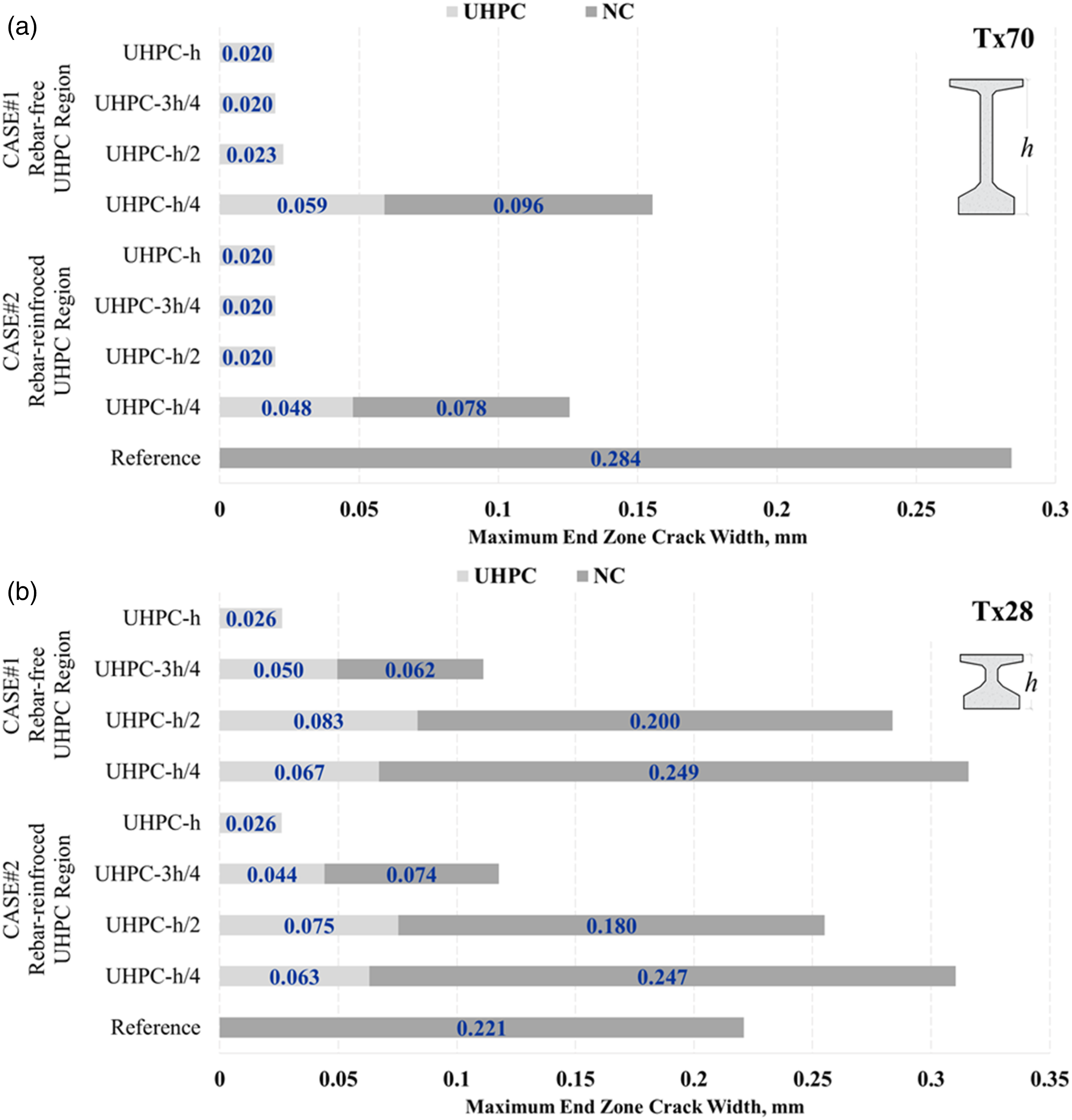
As the UHPC zone length reduced to h/4, the crack width increased significantly in both Case #1 and Case #2. Specifically, for Tx28, the UHPC zone length of h/4 resulted in a crack width in the NC region of 0.249 mm [0.009 inch], which exceeded the reference value of 0.221 mm [0.008 inch]. Hence, the elimination of end zone reinforcement in Tx28 could not be compensated by the use of a short UHPC region (i.e., h/4) to effectively control end zone cracking. Overall, in comparison with the reference models, it is shown that the use of a UHPC zone length equal to or greater than h/2 effectively reduced the crack width in the end zone of Tx70 and Tx28 girders. This finding indicates that UHPC zones as short as h/2 can generally reduce the crack width in the end zone, which is a significantly lower length than those studied previously (Ronanki et al. 2019; Hamilton et al. 2020). The effect of a UHPC zone is further emphasized in Figure 11 which compares the crack width distribution between Tx70-UHPC-h and the associated reference design from Figure 3. Comparison of FEM crack width contours between the (a) Tx70 reference model and the (b) Tx70 with a UHPC zone length equal to (h).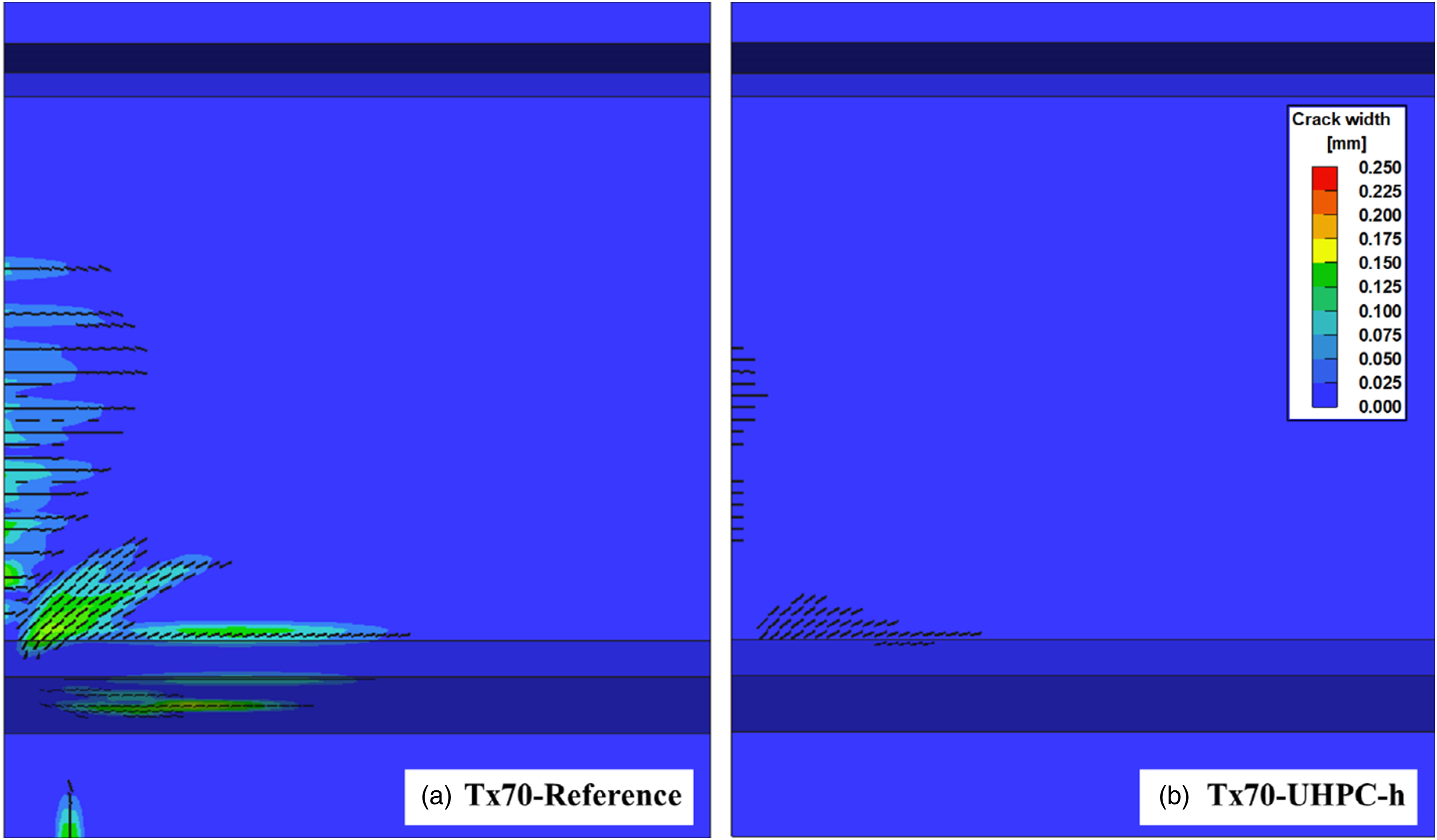
End zone reinforcement stresses
Next, the Rebar-reinforced (Case #2) FEMs discussed in Table 6 were used to calculate the distribution of transverse bar stresses within h from the girder end. Figure 12 presents the bar stresses along the bottom flange-web connection for the hybrid girders in comparison with the reference design and the AASHTO LRFD (2020) allowable stress. It is noted that the flange-web location was selected because it was associated with the larger bar stresses in the girder end. Stress distribution in transverse reinforcement of Case #2 girders. (a) Tx70. (b) Tx28.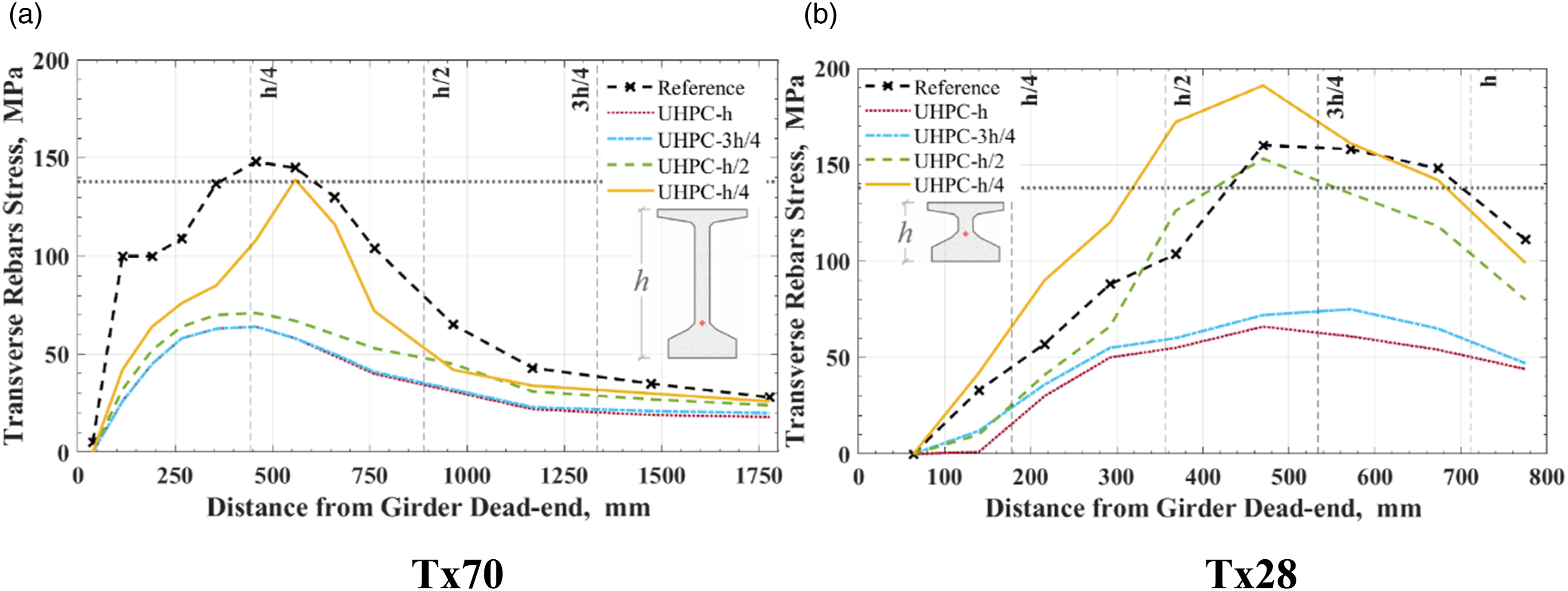
It is shown that the bar stresses were significantly reduced in the girders with UHPC zones, except for Tx28-UHPC-h/4, a result that was expected based on the previous discussion per Figure 10. Apart from Tx28-UHPC-h/4, the bar stresses in the hybrid girders were effectively reduced nearly to or below the AASHTO allowable stress limit of 138 MPa [20 ksi]. More specifically, the reduction was significant for UHPC zone lengths of 3h/4 and h, where the maximum bar stresses were below 75 MPa [10.8 ksi], while, for Tx70, the use of a UHPC zone length of h/4 was sufficient to ensure bar stresses within the AASHTO limit.
Effect of ultra-high-performance concrete on transfer length
This section discusses the effect of UHPC zones on the prestress transfer length. Figure 13 compares the strain profiles of the strand nearest to the web-bottom flange connection, which corresponds to the location of the maximum crack width, for Tx70-UHPC-h, Tx28-UHPC-h, and the reference girders. The figure also marks the transfer length for each strand, which was calculated as the point on the strain profile followed by a strain plateau, indicating that the target prestressing force was practically transferred. This approach for calculating the transfer length is the same as the one used by O’Callaghan and Bayrak (2007). Comparison of the transfer length for Reference and Tx70 and Tx28-UHPC-h designs; where l
t
is the transfer length and d
b
is the strand diameter.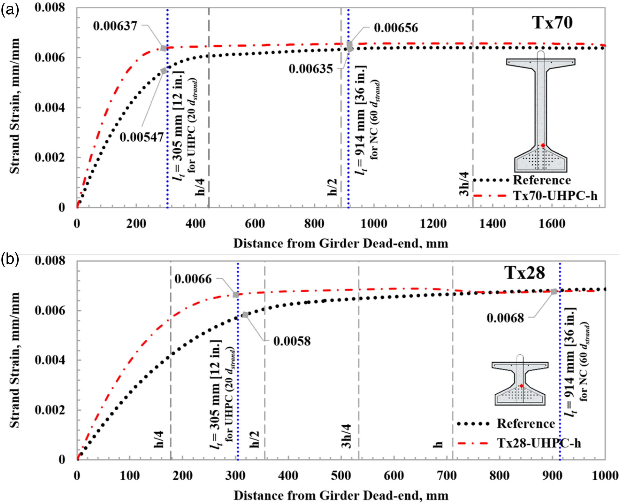
Figure 13 shows that the UHPC zone reduced the transfer length (l t ) from the reference value of 914 mm [36 inches], or 60d b , to 305 mm [12 inches], or 20d b , which is in agreement with observations in the PCI-UHPC Structures Design Guide (Tadros et al., 2021) along with other studies (Hamilton et al., 2020; Tadros and Morcous, 2011; John et al., 2011; Federation Internationale du Beton, 2013).
However, the results in Figure 13 also show that the use of a UHPC zone results in a rapid increase in the prestressing force near the free end of the girder, which is due to the shorter transfer length. For example, the increase in prestressing force for the Tx70 girder was approximately 40% for a distance of h/16 and 27% for a distance of h/8 from the free end.
Depending on the prestressing demand, the significant increase in the prestressing force near the free end of the UHPC zone emphasizes that elimination of transverse reinforcement demands careful attention before it can be generalized. For this reason, the use of a minimum transverse reinforcement amount is recommended. Such a minimum reinforcement could be satisfied with the use of CFRP bars to develop nonmetallic end zones with improved long-term corrosion resistance.
Ultra-high-performance concrete with carbon fiber reinforced polymers in end zone
Based on the previous discussion, it is concluded that the use of UHPC effectively reduces cracking in the end zone of Tx girders. However, it was also shown to increase the prestressing force near the free girder end, suggesting that elimination of end zone reinforcement cannot be generalized and that a minimum amount of transverse reinforcement may be needed. This section investigates the use of CFRP reinforcement for this purpose because of its non-corrosive behavior. To investigate the use of CFRP, the Tx70-UHPC-h/4 (Case #2) model was selected to explore the replacement of steel reinforcement with CFRP, as it was one of the girders that satisfied the AASHTO stress limit, as observed in Figure 12(a).
Study matrix for UHPC-CFRP end zones.
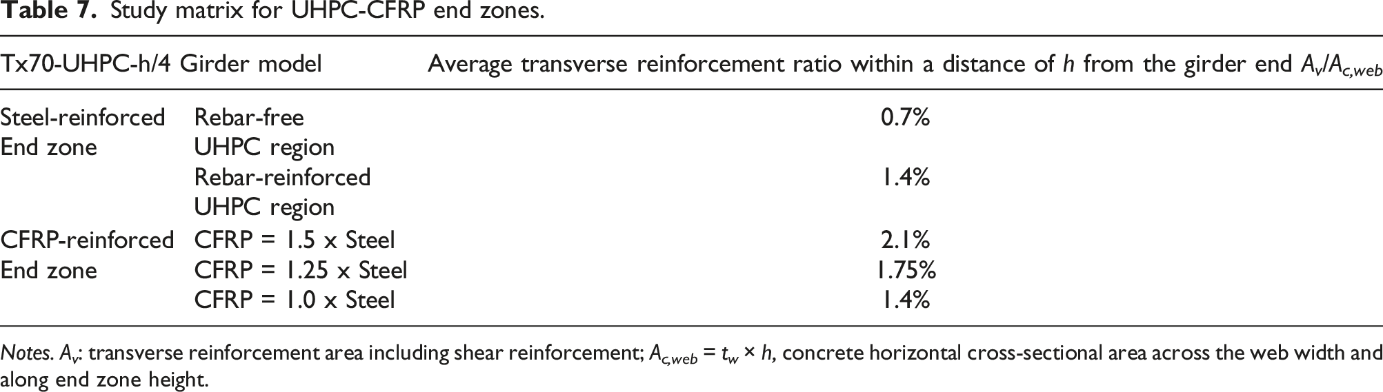
Notes. A v : transverse reinforcement area including shear reinforcement; A c,web = t w × h, concrete horizontal cross-sectional area across the web width and along end zone height.
The UHPC-CFRP girder designs were assessed in terms of maximum crack width in Figure 14, which includes comparisons with Rebar-free (Case #1) and Rebar-reinforced (Case#2) girders from Table 6. It is shown that the UHPC-CFRP zone with 1.75% reinforcement ratio performed equally well as the Rebar-free Tx70-UHPC-h/4 (Case #1), while the UHPC-CFRP zone with 2.1% reinforcement ratio exhibited the smallest crack widths. Overall, these results show that CFRP reinforcement can be considered an alternative to steel reinforcement for conservatism in the implementation of the hybrid girder concept. Maximum crack widths in steel and CFRP-reinforced end zones for Tx70-UHPC-h/4 FE model.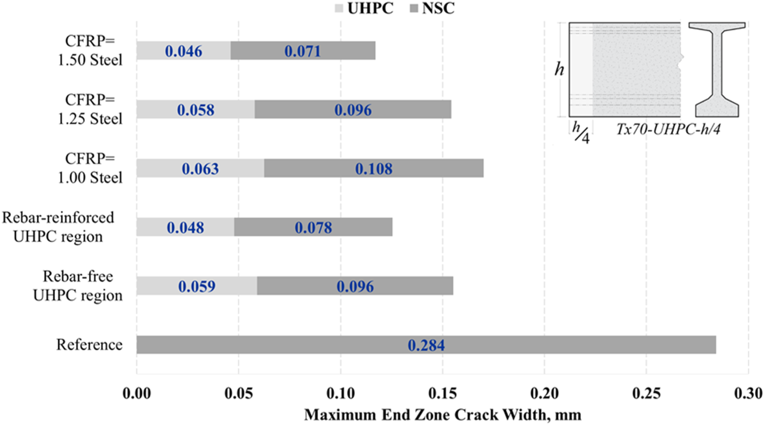
Conclusions
The end zone of prestressed girders is a critical region that requires effective crack control to ensure durability and structural integrity. Previous studies identified the significance of addressing end zone crack problems using various design approaches. In this study, the hybrid girder concept was investigated for Tx girder types using finite element analyses. The analyses were performed using different UHPC zone lengths, ranging from h/4 to h, which was combined with a reduction to the transverse steel reinforcement and its replacement with CFRP bars for improved corrosion resistance. The analysis results were used to quantify the maximum bar stresses and associated maximum crack widths in the end zone. The following conclusions are made: 1. An FEM that can accurately simulate the crack development and bar stresses developed in end zones of prestressed girders was created and validated with experimental data of both NC and UHPC zones. 2. Rebar-free UHPC zones as short as h/2 can effectively restrain end zone cracking and meet AASHTO working stress requirements, which is a 50% length reduction over previous research studies of hybrid girders. 3. UHPC zones as short as h/4 can be effective in deep girders, such as Tx70, if they include transverse reinforcement equal to 50% of that required for NC end zones. However, they cannot effectively control cracking in shallow girders, such as Tx28. 4. The significant increase in prestressing force near the free end of the girders due to the shorter transfer length in the UHPC zone highlights the need for a careful evaluation before eliminating the transverse reinforcement. Hence, the use of a minimum amount of reinforcement is recommended. This requirement can be met with a 1.75% CFRP reinforcement ratio, which also improves the corrosion resistance of the end zone. 5. Future work should investigate the effect of UHPC zones in the shear design of prestressed girders, while the use of the hybrid girder concept may also be studied for post-tensioned anchorage zones.
Footnotes
Declaration of conflicting interests
The author(s) declared no potential conflicts of interest with respect to the research, authorship, and/or publication of this article.
Funding
The author(s) received no financial support for the research, authorship, and/or publication of this article.