
Abstract
This paper describes a program development in testing a 100 kW Permanent Magnet Synchronous Motor (PMSM) using multi-leaf foil bearings with bump foils. The testing program includes the motor speed up to 43000 rpm, and then slow down to zero speed. The orbit of the rotor and the electrical parameters of the motor are obtained. The success in the experiments shows that the design and fabrication of the compliant gas foil bearings and motor can provide a useful guide to the development of an advanced high speed rotating machinery.
Introduction
Demand in industry for high speed and high efficiency electric motors has been on the rise in recent years. The Permanent Magnet Synchronous Motors (PMSM) have a higher energy density compared to other electric machines [1,2]. The high speed PMSM rotor can be supported by the gas bearings, magnetic bearings and rolling element bearings. While the air-lubricated compliant Gas Foil Bearings (GFBs), are self-acting hydrodynamic gas bearings, can be used widely in high speed rotating system. The GFBs have many advantages than the rolling element bearings such as longer life, lower power loss, a wide range of running temperatures, debris tolerance and rotor misalignment [3]. While compared with the magnetic bearings, the cost of the GFBs reduces largely without using the control element.
Zhang et al. studied a simulated rotor system supported onmulti-leaf gas foil bearings for a microturbine [3,4]. The maximum speed of the simulated rotor in [3] can reach 24,000 rpm using a gearbox to increase the output rotating speed of the rotor. It becomes unstable when decelerated to 18000 rpm. After using a pulse turbine instead of the gearbox, the simulated rotor can be operated stably at 45000 rpm [4]. The structural stiffness and damping coefficients of a multi-leaf foil bearing with bump foils is analysed by Tia et al. [5]. The hydrodynamic analysis of multileaf gas foil bearings with back springs are analyzed by Du et al. [6]. All these above gas foil bearings are belonged to the multi-leaf gas bearings, however their supported rotor are not high speed PMSM shaft.
Lee gave a research on the rotordynamic characteristics of a microturbogenerator supported by air foil bearings [7]. Kim evaluated the performances and nonlinear dynamics of 120 kW oil-free gas turbine generator [8]. Heshmat et al. designed and did an experiment on a kW high-speed turbogenerator supported by air foil bearings [9]. Choe BS et al. studied on the rotordynamics of a 30 Hp class motor-generator supported by gas foil bearings [10]. The structures of these GFBs used in the above articles are different fro that of the multi-leaf gas bearings.
We can see that either the common rotor (not high speed PMSM shaft) supported by multi-leaf gas bearings or the high speed motor supported by other types of GFBs (not multi-leaf gas bearings) have been studied extensivelly. Up till now, no relevant literatures about high speed PMSM supported by multi-leaf foil bearings with bump foils are reported. As known, compared with conventional gas foil bearings, the multi-leaf foil bearings have an advantage of more stable operating at high speeds and a high load capacity. Therefore, this paper developed and tested a 100 kW PMSM supported by multi-leaf foil bearings with bump foils.
Test rig and results
The test rig of the PMSM is shown in Fig. 1. The main components contain a high speed Permanent Magnet Synchronous Motor supported by a pair of compliant Gas Foil Journal Bearings (GFJB) and compliant Gas Foil Thrust Bearings (GFTB), a stator divided into 24 slots with a double layer windings shown in Fig. 2. The PMSM, designed as a three-phase/two-poles, has a rated power and voltage of 100 kW and 380 V, respectively.
As shown in Fig. 3, the motor rotor contains a thrust disk, a retaining sleeve which pretects the Sm2Co17 based magnet inserted into its inside from the centrifugal stress. Two eddy current displacement sensors are placed in the thrust disk side and the free end, respectively.
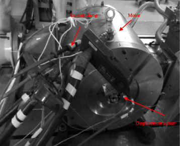
The motor test rig.
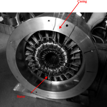
The stator inserted into a casing.
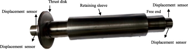
The motor rotor.
The compliant GFJB is designed in a form of a multileaf with backing bump foils structure. One of the top foils, which were made of Inconel X-750, overlaps an adjacent top foil. The remaining four top foils are assembled similarly shown in Figs 4 and 5(a),(b),(d). One edge of both top foils and bump foils is fastened to a key slot of the bearing housing, while the other edge overlaps an adjacent top foil.
The GFTB to be tested adopts an 8 pads and spot-welded structure shown in Fig. 5(c). Both one end of the backing bump foils and top foils are welded on the thrust bearing foundation, and another end is free. In order to maintain smooth face of thrust collar and bearing, the welded spots should be plished. The two compliant GFTBs were designed to load axial forces and hold the rotor axial position.
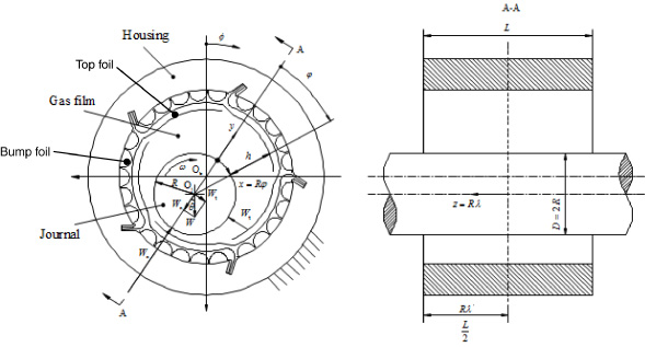
Sketch of Gas Foil Journal Bearing.
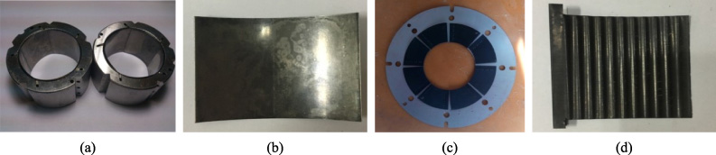
Gas Foil Bearings and Foils. (a) Gas Foil Journal Bearing; (b) Top Foil of Journal Bearing; (c) Thrust gas foil bearing;(d) Bump Foil of Journal Bearing .
The test results mainly contain the magnetic results, electrical results and mechanical results. The magnetic field of the stator and rotor is measured by a Gauss Meter. The electrical variables can be measured and analyzed by a power analyzer containing current clamp and voltage clamp. While the mechanical results can be obtained by postprocessing the data from the displacement sensors.
Figure 6 gives the radial flux density waveform of the rotor at the radial position r = 33 mm and r = 28 mm when the rotor is inserted into the stator. The calculation method of the radial flux density waveform is obtained by the method in [11]. High order harmonics appear for the case of r = 33 mm due to the slots effects of the stator and the maximum radial flux density is 0.66 T. While the maximum radial flux density measured on the rotor is 0.65 T . Thus the numerical result agree well with that of the test result. Thus it may confirms the correct of the design of the rotor.

Radial flux density of the rotor.
The radial flux density of the stator, shown in Fig. 7, obtained by using finite element method when a 9 A current is exerted on. The value equals to 0.00525 T in the center of the stator. After assembling the motor, the measured magnetic field of the stator is 0.00537 T. The discrepancy between them is less than 2.2%.
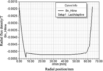
Magnetic field of the stator.
Figure 8 exhibits the electrical results of the motor measured by a power analyzer, which are frequency, Root Mean Squar (RMS) current, RMS voltage and Line voltage waveforms at 43000 rpm, respectively.
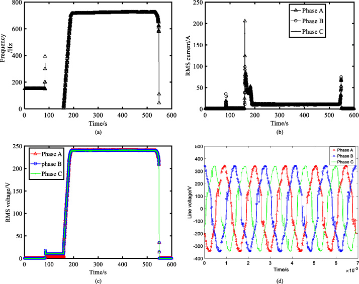
Electrical results of the motor (a) Frequency (b) RMS current (c) RMS voltage (d) Voltage waveform at 43000 rpm.
As shown in Fig. 8(a), the frequency of the motor is jumped up to 400 Hz at the time 90 seconds. This is caused by enable operation of the frequency inverter of the motor. This enable operation of the frequency inverter usually exterts a smaller pulse current to check whether the rotate direction of the rotor is correct. Then, the motor starts up at the time of 159 seconds, and reaches the maximum speed (43000 rpm) at 191.4 seconds and operates about 533 seconds. Finally it deceleates to zero speed.
From Fig. 8(b) and (c), the current at the time 90 seconds is 4 A which is called as a holding current for the enable operation of the motor. The current reaches maximum value to 206 A during start up of the motor. The value is 10 A when the motor operates at the speed of 43000 rpm while the voltage is about 240 V, which is limited by the maximum of the external line voltage of the power.
The line voltage waveforms of the three phases at the speed of 43000 rpm are shown in Fig. 8(d) and are nearly sinusoidal waveform. These results confirm the viability of the designs of the motor.

Results of frequency response function.
Figure 9 shows the frequency response function obtained by modal tests. The single-input and multi-output method is used in the modal tests. The detailed of this is one accelerator fixed on the rotor and a hammer impacted on several points in the longitudal direction of the rotor. The frequency response function of the modal tests is given in Fig. 9, where the different color curves represent the results on of the accelerator when the hammer impacts on the different points on the rotor. As seem in Fig. 9, the first bending frequency is 1792 Hz, meanwhile it is 1820 Hz calculated by using Finite element method. The discrepancy between them is less than 2%. Thus the motor rotor operates in rigid modes in this article.
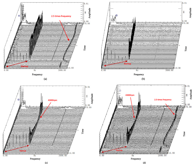
Waterfall of the rotor (a) Horizontal direction of the thrust disk (b) Vertical direction of the thrust disk. (c) Horizontal direction of the free end (d) Vertical direction of the free end.
The waterfalls of the free end and the thrust disk of the rotor in the vertical and horizontal directions are shown in Fig. 10. Both of them mainly vibrate synchronously and their amplitude is relatively small. As compared with that of the vertical direction, a 2.5 times frequency vibration exists in the horizontal direction of the thrust disk. On the contrary a 2.5 times frequency vibration appears in the vertical direction of the free end. Both 2.5 times frequency vibration of the thrust disk and free end may be caused by the five pads (five top foils and five bump foils) of the GFJB. The 2.5 times frequency appears in the different directions of the thrust disk and free end is caused by the characteristic of the GFJB and GFTB.
An interesting phenomenon can be found in the waterfall in both directions of the free end when the rotor operated at 43000 rpm, which the amplitude decreases to a certain value and keeps a few seconds, then increases again.
Besides, we also found that the vibration amplitude increases first and then decreases during the startup of the motor from the waterfalls in Fig. 10. This indicates the GFJBs have been lifted off, which means there is no rubbing between the journal and the top foils of the GFJB.

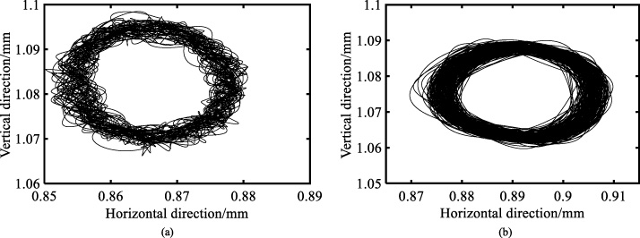
Orbit of the free end (a) 10800 rpm (b) 42718 rpm.
Orbits of the thrust disk (a) 10800 rpm (b) 42718 rpm.
The orbits of the free end at speed of 10800 rpm, and 42718 rpm are shown in Fig. 11 The shape of these orbits exhibits ellipticaly. The maxmium displacement in the horizontal direction is less than 20μm while less than 25 μm in the vetical direction. Thus the amplitude of the vibration is rather small.
Figure 12 shows the orbits of the thrust disk at speed of 10800 rpm and 42718 rpm. The maximum displacement of the horizontal direction and vertical direction is less than 40 μm and 30 μm, respectively. As compared with those of the free end, these values become larger. It may be caused by the smaller preload of the GTFB.
A 100 kW high speed PMSM supported on multi-leaf foil bearings with bump foils is manufactured and tested in this paper. Both magnetic, electrical and mechanical test results are met with the design aims. The PMSM can be operated stably at 43000 rpm. The rotor vibrates synchronously and the amplitude is relatively small. These test results confirm the viability of the designs of the motor and the multi-leaf foil bearings with bump foils.
Footnotes
Acknowledgements
This work is supported by the National Natural Science Foundation of China (Grant No. 51805407), Key Research and Development Project in Shaanxi Province of China (Grant No. 2017ZDXM-GY-054) and Natural Science Foundation in Shaanxi Province of China (Grant No. 2018JQ5148).