



Abstract
This paper presents a multiphysics modeling and design methodology for high speed permanent magnet synchronous motors (PMSM) for electric traction applications. In this proposed methodology, the electromagnetic, thermal and mechanical fields are coupled together. The electromagnetic model is used to analyze the electromagnetic performances and losses of the PMSM, which then feed the thermal and mechanical models. The thermal model focuses on the machine’s temperature rise while the mechanical model is used to analyze the stress distribution of the PMSM. Combined together, a powerful multiphysics model aimed for the design of high speed PMSMs is achieved. The design results prove that the designed PMSM can simultaneously meet the requirements of high power density, high temperature and high reliability.
Introduction
In mobile applications such as the aerospace [1], automotive and marine industries, the electrical machine (EM) required for propulsion and/or traction needs to achieve high power densities, while at the same time being highly robust and reliable. Permanent magnet synchronous motors (PMSM) have been shown to be ideal for high power density [2], but their operating temperatures are typically limited by the rating of the winding insulation [3] and by the demagnetizations aspects of their permanent magnets (PM).
Since the performance of the magnetic materials depends highly on the operating temperature, accurate thermal analysis becomes an important part of the EM’s design process [4,5]. In order to increase power density and efficiency, an analytical thermal modeling method of an induction motor was proposed in [6]. In order to increase force density, a thermal equivalent circuit modeling method coupled with two-dimensional electromagnetic finite element model of a tubular actuator was proposed in [7], and thermal field analysis of an air-core monopole linear motor by adopting a thermal network method was carried out in [8]. To increase the calculation accuracy, the two-dimension electromagnetic finite element model was coupled with three-dimension thermal network and used as fine models in [9].
For high-speed (HS) machines, the mechanical analysis is as critical as the electromagnet and thermal analysis. In [10], an advanced analytical modeling method was proposed for interior PMSMs, with the aim to improve calculation times. The method was verified through finite element (FE) analysis, which is well known to be able to consider complex geometrical and irregular shapes and can also consider the nonlinear parameters of the materials. In [11], FE was used to analyze the electromagnetic, thermal and mechanical aspects of epoxy potting stator in a yokeless axial flux PMSM to reduce the overall weight. In [12], FE was used to design a HS PMSM and analyze electric and mechanical performances.
All the above highlight the importance of coupling the different physics required for the design of a HS machine. While various literatures have discussed and proposed various methodologies related to this subject, however today there is still no clear definition of an optimal multiphysics model that can consider all the required design aspects for a HS PMSM.
Because of the well-known accuracy of finite element method [13,14], this paper, thus proposes a new multiphysics FE-based modeling methodology that aims to bring together all the electromagnetic, thermal and mechanical analyses required to design a HS PMSM (30 kW, 25000 rpm). The model couples the three main fields together in a seamless and inter-active manner in order to calculate the electromagnetic performances, the temperature rise and the mechanical stress distribution of the PMSM. Since the HS PMSMs used for aerospace and automotive applications always operate in high ambient temperature, 90 °C
Multiphysics modeling method
In the design process of a HS PMSM operating in high ambient temperature (100 °C), the temperature and mechanical performances are as important as the electromagnetic performances for the PMSM. In this section, a multiphysics modeling method is introduced and applied to analyze the electromagnetic, thermal and mechanical performances of the PMSM.
Electromagnetic modeling
In the proposed method, 2D nonlinear transient electromagnetic FE analysis is done with the commercial package, ANSYS. The nonlinear influences of the high temperatures on the physical properties of the materials are considered. To adapt to the high ambient temperature, a high temperature rating PM material, 35EH NdFeB, is used, whose maximum working temperature is 200 °C, residual magnetic induction B
r
is 1.23 T and its temperature coefficient is −0.0013∕°C. To get the accurate copper loss, the temperature coefficient of armature resistance is set to be 0.00393∕°C. The corrected equations for skin effect of the resistivity of double-layer stranded winding is shown in (1), where 𝜌
c
is the resistivity modified with the temperature coefficient, s
f
is the slot space-factor, h
c
is the height of the winding, b is the width of the winding, b
s
is the width of the slot, m is the number of the conductors in the height direction, n is the number of the conductors in the width direction, f is the frequency of the current, l is the length of the iron core and l
e
is the half length of one winding including the end length.
Figure 1 shows the flux density distribution of a generic PMSM in the no-load and load conditions separately. To verify the accuracy of the 2D model, the analysis results are compared with those of 3D nonlinear transient FE models. Figure 2 shows the difference of flux density B r in the air-gap between the 2D and 3D models. Figure 3 shows the difference of the output torque between two models. The results show that the difference of the input voltage between two models is smaller than 0.6%. Meanwhile, the differences of flux density between two models and the differences of the torque between two models are both smaller than 2%. The 2D electromagnetic FE modeling method is proved to be an accurate and convenient method for the design of the PMSM.
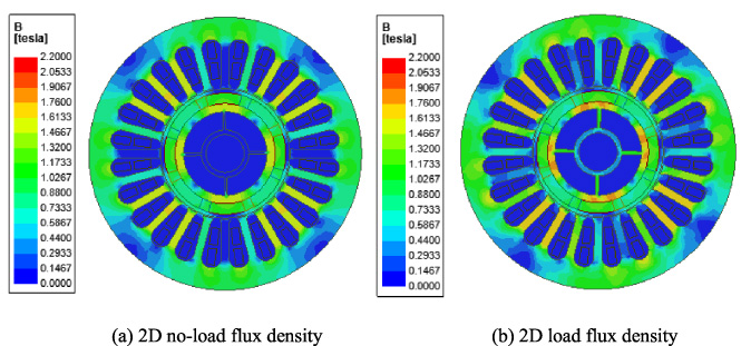
Electromagnetic field flux density.

Comparison of 2D and 3D no-load flux density.
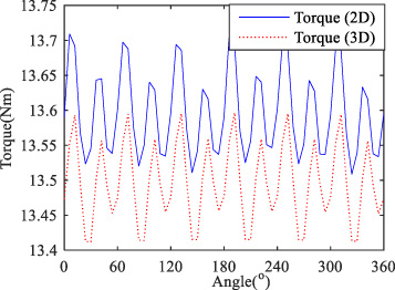
Comparison of 2D and 3D torque.
To analyze the thermal field distribution and temperature rising of the PMSM, 3D nonlinear transient thermal FE model of the PMSM is set up by using the ANSYS software. In the thermal model, the copper loss, PM eddy current loss and core loss data calculated by the electromagnetic model are input as heat sources. Based on the heat conduction equation shown in (2), the temperature field distribution in the PMSM with rated load is illustrated in Fig. 4.
In (2), K x , K y , K z are the thermal conductivity of the materials in the x-direction, y-direction and z-direction, respectively. T = T (x, y, z, t) is the element temperature function, t means time, q is the density of heat resourse, 𝜌 is the density of the materials, c is specific heat, n x , n y , n z are normal vectors, K is the novel vector of thermal conductivity in the outer surface, 𝛼 is the heat release coefficient and T e is the ambient temperature.

Temperature field distribution.
It can be safely stated that the highest temperature of a typical PMSM is usually located in the end part of the windings [16]. Also, the temperature of the middle part of the PM is higher than the temperature of the end parts. Therefore, the maximum temperature of the end part of windings and the maximum temperature of the middle part of the PMs are used as key parameters in the following design.
The coupling method introduces the calculated temperature results back to the electromagnetic model to correct the losses results, and recalculate the temperature field. After two coupling cycles, the temperature used in the electromagnetic model is considered to be accurate enough.
With the calculated temperature from the thermal model, a 3D mechanical FE model is set up to calculate the stress field distribution. This model is mainly used to guarantee that the motor meets the mechanical strength requirement of high speed operating conditions. Ignoring the motion of the stator in axial-direction, and ignoring the influence of bearings and other structure details as chamfers on the stress, the stress field in the PMSM with rated speed of 25000 rpm is shown in Fig. 5, where the equivalent stress is calculated by (3), where σ
r
is the radial stress, and σθ is the tangential stress.
To protect the surface-mounted PMs, carbon fiber is selected to use as a protective sleeve because of the advantages of zero eddy current loss, high yield strength and light weight. From Fig. 5, it can be found that the maximum stress exist in the bottom corner of the weight loss holes of the rotor. The maximum stress of PMs and the sleeve exist in the middle parts above the ribs. The maximum stress of the rotor is much higher than the maximum stress of PMs and sleeve. However, the ultimate yield strength of the rotor material, 17-4ph, is about 1100 MPa, which is also much higher than that of the PM and sleeve materials. Therefore, it can be concluded that the NdFeB PM and the carbon fiber sleeve are more sensitive to stress than the rotor. The maximum stress values of the PMs and sleeve are therefore used as key parameters in the design process, explained in the following sections.
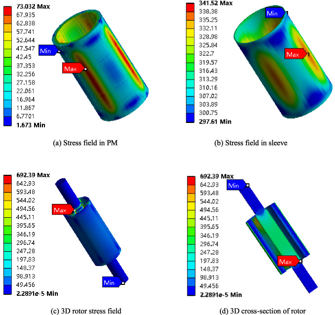
Stress field simulation results.
In this section, the design and quasi-optimization of the PMSM based on the above mentioned multiphysics models is carried out. The process is shown in Fig. 6. According to the basic requirements as output power and voltage amplitude, an initial construction of the PMSM is first established. By using the multiphysics models, the slot/pole ratio, L/D ratio, split ratio, tooth dimensions and PM dimensions of the PMSM are varied to get the relationship between the dimensions and the performances. To meet the requirement of high power density, high rated speed and high ambient temperature, the following restrictive conditions in (4) are set and used to quasi-optimize the PMSM. Finally, the parameters of the PMSM with optimized dimensions are compared with those of the original one to illustrate the improvements of the performances.

Design process of PMSM.
The number of pole pairs for high speed PMSMs is usually less than 3 to limit the switching frequency of the inverter. For the PMSM with rated speed 25000 rpm, the pole pair is set to be 2. The main dimensions of the original design are shown in Table 1.
This section is focused on the analysis of the influence of the slot/pole ratio and the length/diameter (L/D) ratio on the performances of the PMSM. To selecte the appropriate slot/pole ratio, four typical slot/pole ratio, 6 slot-4 pole, 12 slot-4 pole, 24 slot-4 pole and 36 slot-4 pole are applied in the original design. The structures of the PMSM with the four pole/slot ratios are shown in Fig. 7.
Initial motor parameters
Initial motor parameters
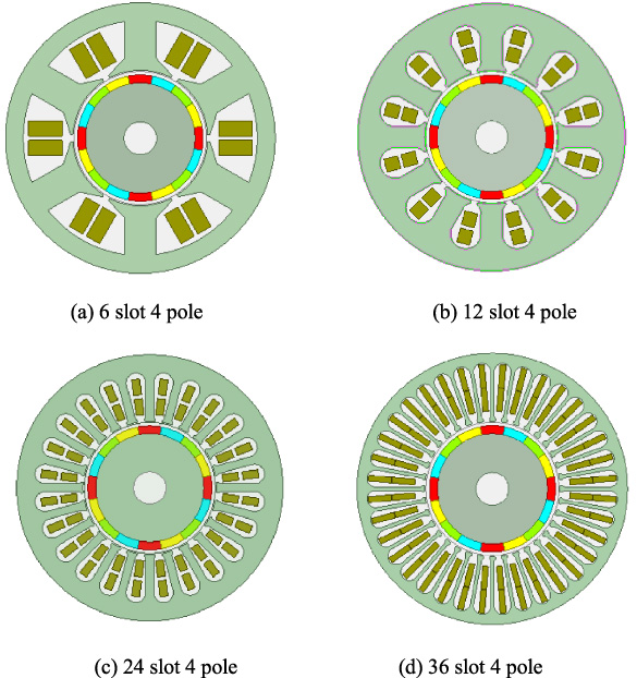
Structure of PMSM with different slot/pole combinations.
By keeping the overall volume, the permanent magnet volume, and the current density constant, the variation of the electromagnetic performances with the slot/pole ratio are calculated and shown in Fig. 8. The abscissa of Fig. 8 is the ratio of the effective length of the stator core (L) to the outer diameter of the stator (D). From Fig. 8, it can be found that the 24 slot-4 pole topology and the 36 slot-4 pole topology can provide higher torque density and lower torque ripple than the other topologies. Due to the voltage of the 36 slot-4 pole topology is too high, it could not meet the restrict condition of voltage <180 V. The 24 slot-4 pole topology is the most suitable topology for the PMSM.
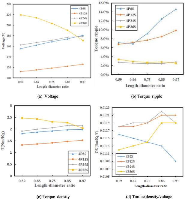
Influence of slot/pole and L/D on electromagnetic performances.
For the 24 slot-4 pole PMSM, the variation of torque ripple with the L/D ratio can be ignored. Although the input voltage amplitude and the torque density both decrease with the increment of the L/D ratio, the ratio of the torque density to input voltage would get the maximum when L/D is 0.85. At this time, the PMSM would output the highest torque with the same outer diameters and the same input voltage.
The variation of the thermal and the stress performances with the L/D ratio are shown in Fig. 9. It can be found that the variation of temperature rising is much less than the variation of stress performance. With the increment of the L/D ratio, the stress of the PM decreases lineally, but the changes of the stress of the sleeve are opposite. When L/D is 0.85, the maximum stress of the PM is about 80 Mpa, which just meets the restrictive condition.
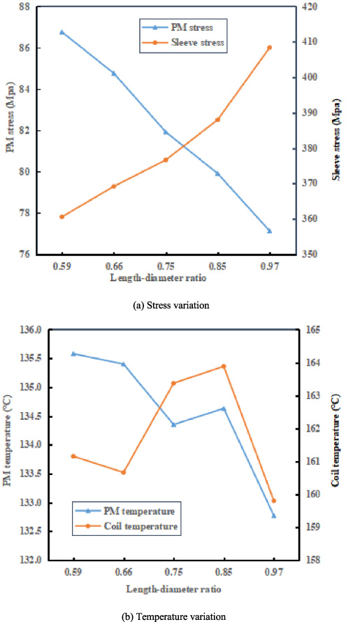
Influence of L/D on temperature and stress performance.
The split ratio K sp is the ratio of the inner diameter (D i ) to the outer diameter of the stator (D). It is also an important design item for the PMSM. When L/D is 0.85, the variations of the electromagnetic performances with the split ratio and the slot/pole ratio are shown in Fig. 10. The results also prove that the 24 slot-4 pole topology can provide higher torque density per voltage than other topologies. Meanwhile, the torque density per voltage of the 24 slot-4 pole PMSM is maximum when the split ratio is about 0.4–0.5.
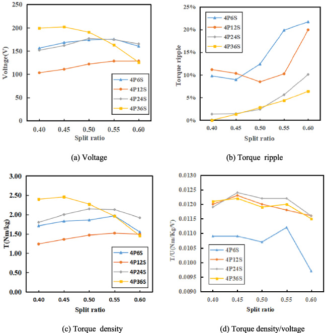
Influence of split ratios on electromagnetic performances.
Although the increment of the split ratio could decrease the stress of the sleeve and the PM temperature as shown in Fig. 11, the stress of PM and the torque ripple would be increase at the same time. In order to meet the PM stress and torque ripple conditions, the split ratio should less than 0.5. All the analysis results show that the best split ratio is 0.45.
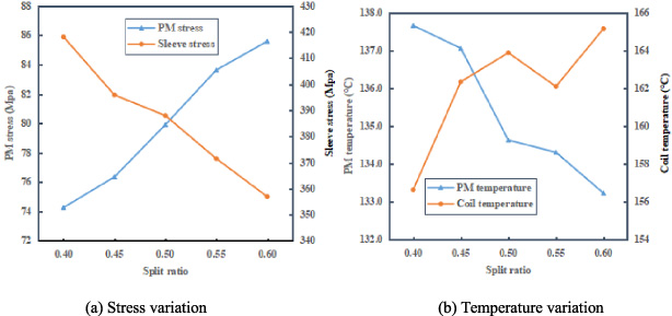
Influence of split ratio on temperature and stress.
Tooth width would influence the torque ripple and the magnetic field distribution in the yoke and slot. Keeping the slot area constant, the increment of the tooth width would decrease the slot width, increase the slot height and decrease the stator yoke height. In this paper, the influences of the tooth width on the multiphysics performances of the PMSM are analyzed. The ratio of the stator yoke height to the tooth width is changed from 2.46 to 3.22. The variations of the performances are shown in Fig. 12 and Fig. 13. From Fig. 12(a) and Fig. 13, it can be found that the change of the torque density is less than 3.5%. The change of the stress is less than 1 Mpa. The change of the torque ripple is higher, but is still only changed from 2.2% to 3.9%. The change of the PM temperature is less than 3 °C.
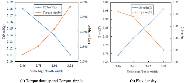
Influence of tooth width on electromagnetic performances.
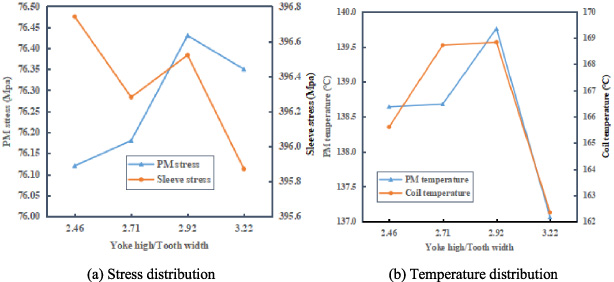
Influence of tooth width on temperature and stress performance.
The change of the magnetic flux density is more obvious than other parameters. As shown in Fig. 12(b), the flux density in tooth would increase rapidly with the decrement of the tooth width. When the ratio of the stator yoke height to the tooth width is 2.71, the flux density is about than 1.8 T, which is the knee point of the B-H curve of the iron core.
In order to decrease the saturation degree of the iron core to less the iron loss, the ratio is selected to be 2.71.
A quasi-Halbach PM array is applied in the PMSM to enhance the flux density and torque density [17]. The radial magnetized PMs are called the main poles, and the circumferential magnetized PMs are called auxiliary poles. The width ratio between the main pole and the auxiliary pole directly affects the harmonics of the flux density in the air-gap. Therefore, the multiphysics performances of the PMSM with different main and auxiliary pole ratios are analyzed in this part.
Figure 14(c) shows that, with the variation of the width of the main pole, the change of the torque ripple is higher than the change of the torque density. The change of the torque density is less than 2%. The torque ripple changes from 4.0% to 1.0%. When the width of the main pole is 13.85 mm, the torque ripple is minimum. The variation of the PM’s temperature is similar to the variation of the torque ripple. The harmonics in the flux density would also influence the PMs’ loss. When the width of the main pole is 13.85 mm, the maximum of the PM is only 138 °C, as shown in Fig. 14(a). The changes of the stress performances and Fig. 14(b). Because of the nonuniform direction of centrifugal forces, the maximum stress on the PMs and the sleeve would increase with the increment of the width of main pole, especially when the width of main pole is higher than 15.64 mm.
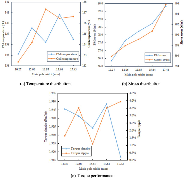
The influence of main pole width on performances.
Cutting weight loss holes in the rotor can decrease the rotor’s mass to further increase the torque density of the PMSM. In this part, two types of weight loss hole structures are used in the PMSM, as shown in Fig. 15. Their influences on the performances are analyzed based on the proposed multiphysics model.
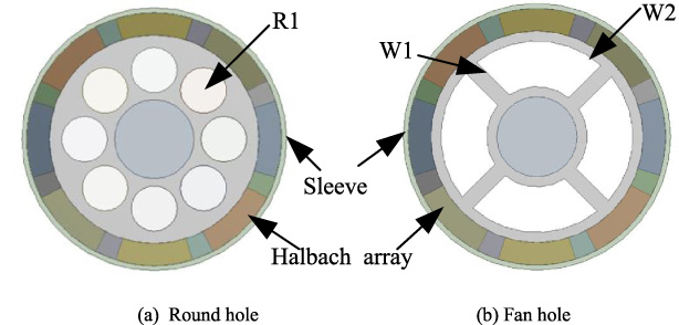
Two types of weight loss hole.
The electromagnetic results show that the changes of the hole diameters don’t have obvious effect on the electromagnetic performances of the PMSM. The reason is that quasi-halbach PM array is the main path for the magnetic flux of the rotor. When the hole diameters varies in a certain range, the saturation degree of the rotor core changes little. Thus, the variation of the torque mean value, the torque ripple and the power all can be ignored. Because the losses of the PMSM change little at the same time, the thermal analysis results prove that the variation of the temperature with the dimensions of the weight loss hole also could be ignored. The influences of the dimensions of the round weight lighting hole on the stress performance are shown in Fig. 16. The advantage of the round hole is that the maximum stress on the PMs decreases with the increment of the radius. But the stress on the rotor increases very quickly at the same time. When the radius is more than 4.9 mm, the rotor core is deeply saturated. Torque density of the motor also begins to decrease with the increment of the radius. To get the maximum torque density and the minimum PM stress, the best radius of the round hole is 4.9 mm. At this time, the maximum torque density is 1.9971, the maximum stress on PMs is 77.8 MPa.
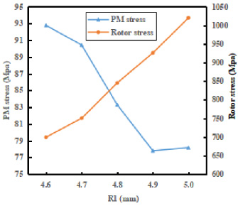
The influence of the radius on the stress.
The influences of the dimensions of the fan one on the stress performance are shown in Fig. 17. It can be found that the stress on the PM and the stress on the rotor can get a good balance when W1 = 1.5 mm and W2 = 3 mm. At this time, the maximum stress on PMs is 73.0 MPa, the maximum stress on rotor is 688.4 MPa, and the maximum torque density is 2.0031. The fan weight loss hole can provide the less stress and higher torque density than the round one. It is more suitable for the proposed PMSM.

The influence of W1 and W2 on the stress.
Based on the contents above, the optimized dimensions of the PMSM are shown in Table 2. The performances of the optimized PMSM are list in Table 3.
Main dimensions of the quasi-optimized PMSM
Main dimensions of the quasi-optimized PMSM
Comparison of the multiphysics performances
Compared with the original one, the quasi-optimized PMSM has higher torque density, higher efficiency, lower total mass, lower torque ripple, lower PM stress and similar PM temperature. The torque density is increased by 4.17%. The torque ripple is reduced by 46.27%. The cogging torque is reduced by 60%. Although the quasi-optimized PMSM has lower power factor, the value of about 0.95 is still acceptable for the PMSM.
In this paper, a multiphysics modeling and design method for a high torque density, high temperature PMSM is proposed. Based on the coupling multiphysics models, the electromagnetic, thermal and mechanical performances of the PMSM are analyzed systematically. The analysis results show that, compared with other slot/pole topologies, the 24 slot 4 pole motor can provide the highest torque density and lowest torque ripple. The PMSM can get highest torque density and proper stress distribution when L/D is 0.85 and split ratio is 0.45. When the width ratio between main pole and auxiliary pole is 2.2, the cogging torque of the motor can be effectively decreased. For the PMSM, the fan weight loss hole can get higher torque density and lower stress than the round one. By comparing with the original PMSM, the performance improvement has been validated.
As further work, the mechanical construction and the processing technology will be researched on, after which a full prototype of the PMSM will be constructed.
Footnotes
Acknowledgements
This work was supported in part by the National Science Foundation of China under Grant 51677172, in part by the Zhejiang Provincial Natural Science Foundation of China under Grant LY19E070006.