
Abstract
Applied loads in bolted geometries of safety critical components can vary with time and operating conditions. Structural integrity and remaining life assessments of such components in aging industrial plants must consider the resultant changes in damage accumulation rates and acceptable defect sizes. Two case studies are presented that demonstrate the effect of bolt pre-load on creep and fatigue lives as well as on the acceptability assessments of defects. In the first case the sensitivity of creep damage accumulation and crack propagation rates to bolt pre-load in high temperature flanged connections are considered. Predicted results were found to compare well with actual damage quantified on a high pressure turbine loop pipe flange connection. It was shown that decreased pre-loads, in this case, leads to an increase the allowable safe defect size during assembly at room temperature. In contrast to this the second case study of corrosion fatigue cracking in a boiler water circulating pump illustrates that an increase in bolt pre-load leads to an increase in fatigue initiation life, a decrease in fatigue crack propagation rate and an increase in the acceptable defect size. Strain gauge measurements of bolt and casing strain, which correlated well with finite element calculations, indicated the necessity for close control of bolt pre-load during assembly to ensure specified levels are attained. In both cases metallurgical analysis and structural integrity assessments of cracked and excavated geometries were conducted which enabled limited continued operation of the components after which repairs and/or replacements will be implemented.
Introduction
Bolted connections of major components are common in industrial plant. Many of these connections are on components or systems which require high levels of integrity as failure could result in catastrophic consequences and/or injury or fatalities. In most of these cases a bolt pre-load to be applied during assembly at room temperature is specified in the design. Control of this pre-load is mostly done indirectly such as for example the arc of turn method and the torque method. If applied without the necessary caution and attention to detail significant over or under pre-load can result. This may result in a significant reduction in remaining safe operating life. Two case studies are presented. In the first case the effect of lowering pre-load on the defect tolerance in a high temperature flanged connection is investigated. Secondly, the effect on low cycle fatigue life due to the increase in tie bolt pre-load in a boiler water circulating pump bowl was investigated.
High temperature flanged connections
Flange design
Flanged connections on high pressure and temperature (>400 °C) main steam, auxiliary steam, turbine loop pipes and other systems are commonly used throughout industry. Some of these connections make use of the so called ‘raised face’ (RF) flange design and is usually face-to-face (i.e., no gasket). The reason for the raised face is to increase the contact pressure between the flanges and in so doing increase the pressure containment capacity. These flanges have a gap between the flange bolt faces (Fig. 1). Note that other naming conventions or similar designs, where there is a gap between flanges and an induced bending moment, may exist. Recent non-destructive-testing (NDT) inspections detected significant creep damage and cracking on some RF flanges that have been in operation for more than 200 kh [10]. Historical records indicate that cracking has been seen as early as 165 kh and 4 re-tightening cycles, which typically occur during general overhauls (GO). Creep damage and cracking can be significant and pose a threat of leaking and/or failure if left unattended. Operating temperature in this case is 535 °C.
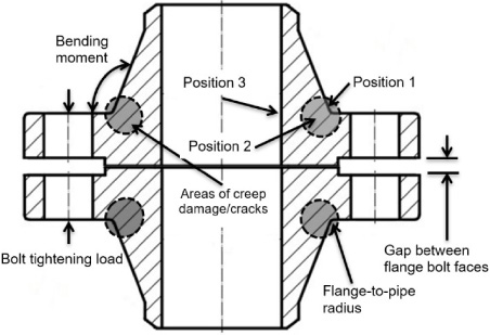
Typical design of a ‘raised face’ flange. Showing areas where creep damage and cracking are expected as well as calculation positions.
The subject flanges were manufactured from a CrMoV steel (21CrMoV-511) and the bolts and spacers from X19CrMoNbVN11-1 material. Material properties can be found in [2].
Mechanism of damage
Bolting of the RF flange to design pre-load leads to high local stresses and cracking in the bolt-hole recesses and the flange-to-pipe radii (Fig. 2) due to bending of the flange. The pre-load in the bolts and high bending moment induced tensile stress in the flanges reduce in operation due to creep relaxation but reach a nominally constant value after approximately 20 kh. Although stress in the flanges reduce correspondingly it cycles around high enough levels for creep damage to accumulate with continued operation. Creep damage accumulation is exacerbated by repeat re-tightening, usually during general overhauls, as well as due to the multi-axial stress state (i.e., multi-axial as opposed to uni-axial) in the flange-to-pipe radii. Mult-axial stress states are known to reduce material creep ductility. Actual creep damage accumulation and creep crack growth rates are dependent on material properties which can vary significantly and hence the time at which damage and/or cracking is first detected.
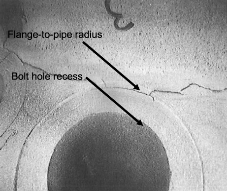
Cracking in bolt recess and flange-to-pipe radius.
The initial bolt force (F) and bolt stress (𝜎) at room temperature can be calculated from:
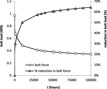
Reduction in bolt load due to creep relaxation.
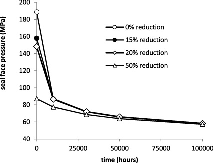
Effect of bolt preload on seal face pressure.
It is well known that the state of stress in a component influences the creep rupture life whilst creep rupture properties are typically obtained from uniaxial creep tests. To account for the multi-axial stress state Othman and Hayhurst [8] developed a formulation to calculate a representative stress (𝜎
rep
) which can then be used with the uniaxial creep rupture data to predict rupture life in the component:
The Cocks–Ashby relation [4] is one method to calculate the ductility factor (DF), i.e. the ratio of the multi-axial ductility to the uniaxial ductility as a function of the tri-axiality factor (TF) which is given as:
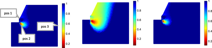
Tri-axiality factor (TF) (left), ductility factor (DF) (centre), and time to rupture reduction factor (TR) (right) for a test case.
Position 1 is between two bolt holes on the external surface, position 2 is a volumetric position below the bolt-hole recess and position 3 is on the internal diameter in-line with the bolt-hole recess.
Although the effective stress at position 2 is not the highest the creep damage fraction after 250 kh is the highest relative to the other two positions. This is due to the tri-axial state of stress in this position. Due to the higher tightening stress the creep damage fraction at position 2 is also higher than at position 3. Note that only the damage fraction for position 1 is affected significantly by re-tightenings (Fig. 6).
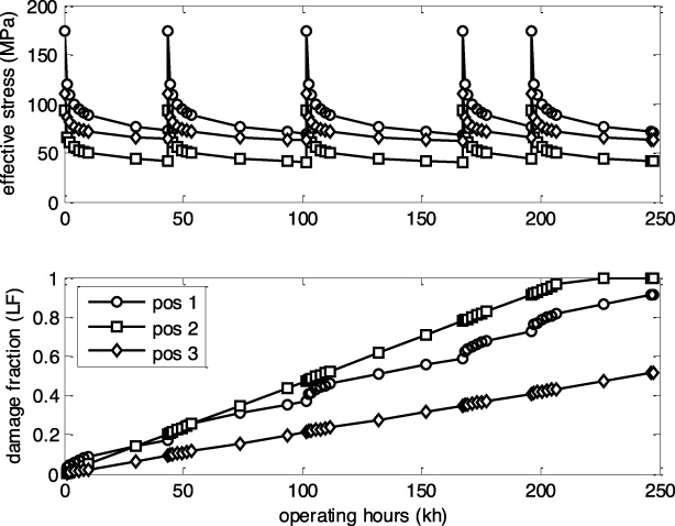
Stress history and calculated creep damage fraction.
Background
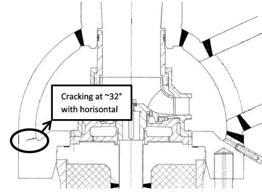
Inspection of a boiler water circulating pump (BWCP) by magnetic particle (MT) testing and phased array (PAUT) inspection indicated significant cracking (full circumferential) from an internal radius position (Fig. 7). PAUT indicated intermittent defects up to a maximum depth of approximately 33 mm (in a wall thickness of ∼60 mm). Material replications were evaluated under a light microscope and cracking was found to be transgranular, multi-facetted, branched with blunt tips and oxide filled (Fig. 8). It was concluded that the damage mechanism was low cycle corrosion fatigue. All defects were carefully excavated up to a maximum depth of 24 mm at an angle of approximately 32° [11].
Multiple linear indications detected on the inner radius of the BWCP.

Photomicrograph showing the defects at 50× magnification. (5% Nital etch.)
The BWCP bowl is manufactured from 15NiCuMoNb5 (WB36) material. As the operating temperature is ∼355 °C a sample was extracted and a Charpy ISO-V impact test was conducted to check for temper embrittlement. An impact energy significantly higher (233 J) than the minimum specification, i.e. 40 J [12], was obtained which can be correlated to approximately 92 MPa
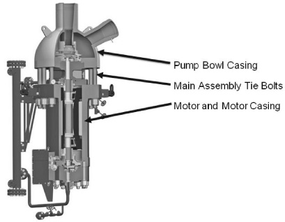
Typical layout of BWCP complete with motor and heat exchanger [7].
Tightening of the assembly tie bolts are affected by heating of the bolts and turning to a pre-set revolution to obtain a design bolt elongation of ∼2 mm which implies a bolt load of ∼700 kN. To ensure correct installation two high temperature strain gauges were fitted to a tie bolt as well as two positions on the BWCP bowl using standard foil type rosette strain gauges. Initial results indicated an incorrect installation (low tie bolt load) and the pump was re-assembled to a tie bolt load of 656 kN. A cyclic symmetric finite element model containing a sector of the BWCP bowl, heat barrier, motor casing and one tie bolt was developed. Calculated stress results for the assembly condition (i.e. bolt load only, 656 kN) at the two bowl strain gauge positions compared fairly well with measured results which gives confidence in applying the FE model for further analyses (Fig. 10).
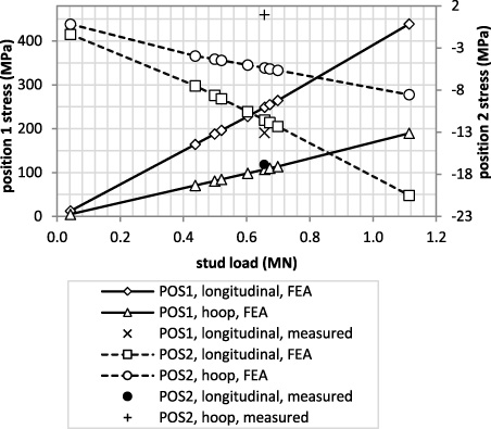
FE (lines) and measured (single point data) stress response at strain gauge position 1 (POS1) and position 2 (POS2) for the pre-load case (i.e. 0 MPa internal pressure).
Stress intensities for a range of crack depths were calculated by directly modelling the cracks in the FE software (Ansys 17.1) for full load conditions i.e., internal pressure and bolt load. Based on a conservative material toughness of 66 MPa
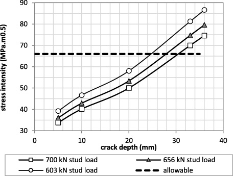
Stress intensity increase as a function of crack depth.
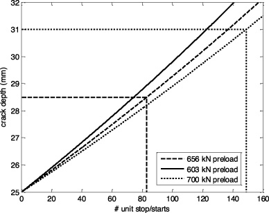
Crack propagation from an assumed 25 mm initial crack depth, 15 pump starts per unit start and 10% higher loads.
Primary loading driving fatigue initiation and propagation was assumed to be due to the internal pressure cycles. Assuming an initial crack depth of 1 mm at the base of the excavated geometry, i.e., an initial crack depth of 25 mm, the number of unit starts allowed to reach the critical crack depth was calculated. The number of pump cycles (stop/starts) per unit stop/start was reported to be 6. To account for additional un-reported cycles and other possible transient effects this value was increased to 15. A 3rd order polynomial fit to the 3D finite element calculated stress intensities as a function of the crack depth was done and the resultant equation is:
The effect of over and under pre-loading of bolts used in major structural connections were demonstrated at the hand of two case studies. In the first case it was shown that the allowable crack size during re-tightening at room temperature increases with a reduction in pre-load. In the second case it was shown that an increase in the tie bolt loading of a BWCP bowl to motor connection is advantageous in terms of allowable crack depth as well as fatigue life. It is thus of upmost importance that the tightening of these connections be controlled to obtain the desired design pre-loads to manage component life expectancy.
Footnotes
Acknowledgements
The authors wish to acknowledge inputs from Dr Mark Newby, Mr Rohit Bhagwandas and Mr Henrico van Rooyen for assistance with strain gauging. Eskom is thanked for the opportunity to report and present this work.
Conflict of interest
None to report.